Bi-planar coil assemblies for producing specified magnetic fields

Inactive Publication Date: 2005-05-19
THE UNIV OF QUEENSLAND +1
View PDF19 Cites 4 Cited by
  • Summary
  • Abstract
  • Description
  • Claims
  • Application Information

AI Technical Summary

Benefits of technology

[0072] (3) the third and fourth coils are shielding coils that serve to reduce the magnitude of the magnetic field produced by the bi-planar co

Problems solved by technology

On the other hand, it is possible that complicated magnetic fields (with tesseral components, for example) may be difficult to design by this method, particularly in view of the number of numerical iterations required in the simulated annealing technique.
As expected, the governing equations are so ill-condi

Method used


Image

  • Bi-planar coil assemblies for producing specified magnetic fields
  • Bi-planar coil assemblies for producing specified magnetic fields
  • Bi-planar coil assemblies for producing specified magnetic fields

Examples


example 1

5.1 EXAMPLE 1

The T00 (Constant Field) Bi-Planar Coil

[0167] In this example, the method of the invention is used to design shielded and unshielded bi-planar coils that are intended to produce symmetrically located T00 fields within the primary bi-planar coil. For this coil, the target fields are simply constants, and so HX is simply a constant on each of the three pairs of target planes. We therefore set

HTX(c1; y, z)=Hmax

HTX(c2; y, z)=Hmax

HTX(c3; y, z)=0.  (5.2)

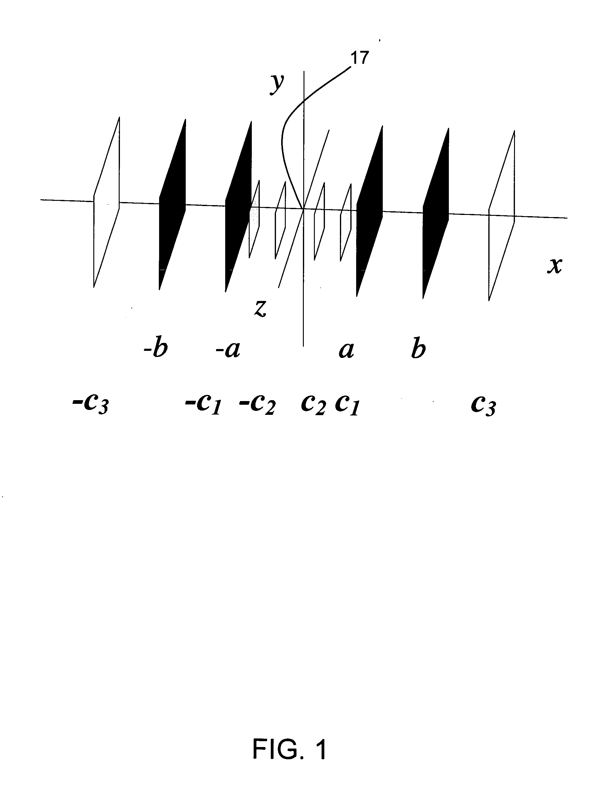
Here, the constant transverse magnetic field within the primary coils has been assumed to take the value Hmax=1 amp / metre. The target field at x=±c3 is set to zero, reflecting the intended function of the shields. Since the T00 field is even in the x-coordinate (it is constant), the primary coil windings on the plane at x=−a are in phase with those on x=a, and the same is true for the shields on the planes x=±b. (This even target field requires the last term in equation (4.11) to take a plus sign).

[0168] To begin, the c...

example 2

5.2 EXAMPLE 2

The T11 Bi-Planar Coil

[0176] As a further illustration of the use of this invention, shielded bi-planar coils will be designed in this section, both for symmetric and asymmetrically located T11 fields. The transverse magnetic field component for this case has the general form HX (x, y, z)=C11x with C11 an arbitrary constant. It follows that the target fields on the three pairs of target planes used in this invention must be given by the equations HTX⁡(c1;y,z)=Hmax⁡(c1a)⁢⁢HTX⁡(c2;y,z)=Hmax⁡(c2a)⁢⁢HTX⁡(c3;y,z)=0.(5.3)

Here, the constant Hmax is now the maximum magnetic field strength (in the x-component) on the plane x=a of the primary coil. Its value is set to 1 amp / metre here, for illustrative purposes. As this target field is now anti-symmetric in x, it follows that the coils on the opposing planes of the bi-planar coil (and also the shields) are counter-wound. This is the case discussed explicitly in Section 4.3.

[0177] The primary winding for a shielded T11 coil in...

example 3

5.3 EXAMPLE 3

The T21 Bi-Planar Coil

[0184] Another illustration of the use of this invention concerns the design of shielded bi-planar T21 coils. The technique has been used to design both symmetric and asymmetrically located fields, although only the latter case will be discussed here.

[0185] The transverse component for a symmetrically located T21 magnetic field has the general form HX (x, y, z)=3C21xz, where C21 is again an arbitrary constant. For a field that is asymmetrically positioned with respect to the origin, it therefore follows that the target fields take the forms HTX⁡(c1;y,z)=Hmax⁡(2⁢c1a)⁢Z2(q-p)HTX⁡(c2;y,z)=Hmax⁡(2⁢c2a)⁢Z2(q-p)HTX⁡(c3;y,z)=0.(5.4)

[0186] Again, the constant Hmax is set to the value 1 amp / metre here, for illustrative purposes. This field (5.4) is also anti-symmetric in x, as for the case discussed in Section 5.2, and so the coils on the opposing planes of the bi-planar coil and shield are also counter-wound. The quantity Z2 in equations (5.4) is the co...


PUM


Abstract

Bi-planar coil assemblies are disclosed which have DSV's whose centers are offset by distances D from the origins of x,y,z-coordinate systems, where said origins of x,y,z-coordinate systems are coincident with the geometric centers of the coils. The distances D can be of the order of 10-20 centimeters or more. The bi-planar coil assemblies can be used in MRI applications to reduce the feeling of claustrophobia experienced by some subjects. The assemblies also can facilitate the imaging of various joints, including the wrist, elbow, ankle, or knee.

Description

FIELD OF THE INVENTION [0001] This invention relates to bi-planar coils for producing desired (specified) magnetic fields, and to certain preferred methods for designing such coils. [0002] The coils of this invention are particularly suitable for use in magnetic resonance imaging (MRI) equipment. In that application, bi-planar coils enable high-resolution medical imaging to be performed in a manner that reduces the claustrophobia experienced by many patients, and also allows access by medical specialists. However, the application of the present invention is by no means restricted to MRI technology, and is available in any equipment for which parallel plates might be used to generate a desired magnetic field, e.g., a desired stationary magnetic field. Thus it is envisaged that the present invention may also find application in the design of wiggler magnets in synchrotron technology (see, for example, R. A. Cover, G. Rakowsky, B. L. Bobbs and P. K. Kennedy, 1995, Undulator design for ...

Claims


Application Information

Patent Timeline
IPC IPC(8): A61B5/055G01R33/38G01R33/385
CPCG01R33/3806G01R33/381G01R33/3815
Inventor FORBES, LAWRENCE KENNEDYCROZIER, STUART
Owner THE UNIV OF QUEENSLAND
Why Eureka
Try Eureka