Antenna with virtual magnetic wall

a virtual magnetic wall and antenna technology, applied in the direction of antenna earthings, waveguide horns, radiating elements structural forms, etc., can solve the problem that the vmw generates constructive interference of the electric field, and achieve the effect of enhancing the near-field directional characteristics

Inactive Publication Date: 2005-05-19
XELLANT
View PDF7 Cites 39 Cited by
  • Summary
  • Abstract
  • Description
  • Claims
  • Application Information

AI Technical Summary

Benefits of technology

[0010] It is an object of the present invention to provide improved structures and methods for directing a radiated electromagnetic field. It is a further object of some aspects of the present invention to provide antennas with enhanced near-field directional characteristics.

Problems solved by technology

As a result, unlike electrically-conductive reflectors, the VMW generates constructive interference of the electric field.

Method used


Image

  • Antenna with virtual magnetic wall
  • Antenna with virtual magnetic wall
  • Antenna with virtual magnetic wall

Examples


Embodiment Construction

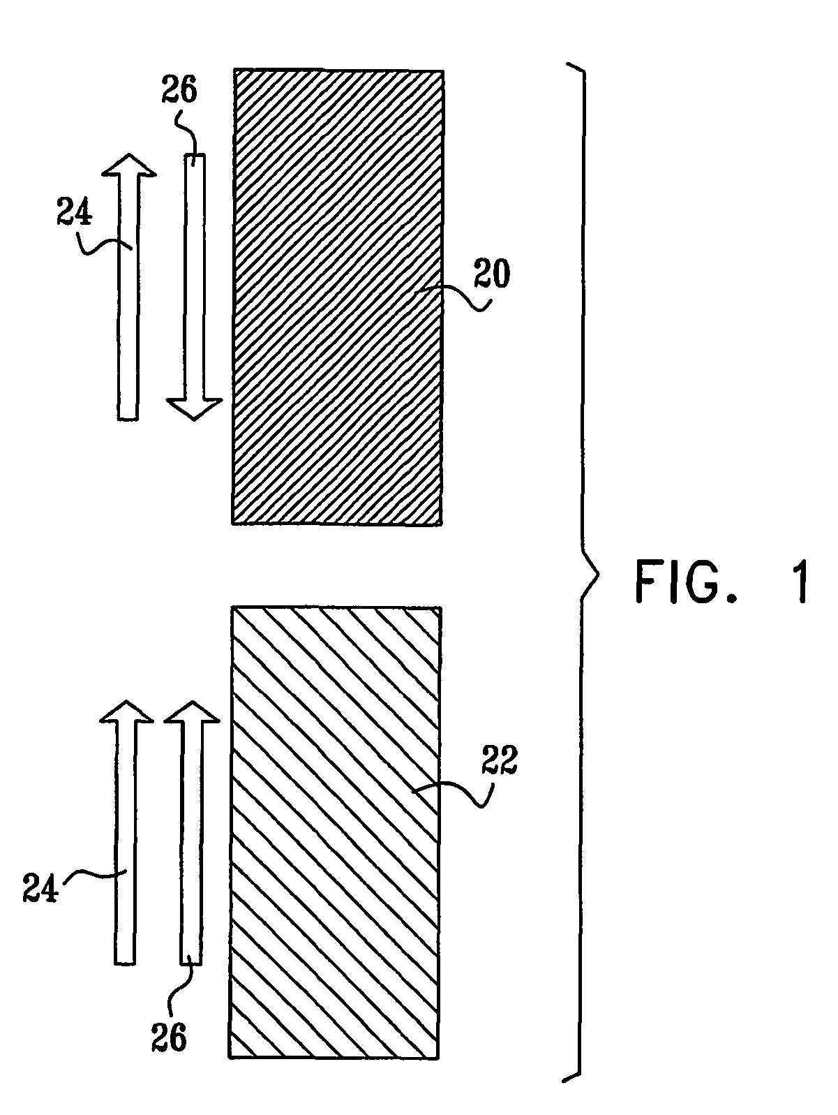
[0048] Reference is now made to FIG. 1, which is a schematic side view of a perfect electrical conductor 20 and a “perfect magnetic conductor”22, on which an electromagnetic field is incident. A first arrow 24 shows the phase of the incident electric field component tangential to the surface of conductors 20 and 22, while a second arrow 26 shows the phase of the reflected electric field. While electrical conductor 20 reflects the electric field 180° out of phase with the incident field, magnetic conductor 22 reflects the electric field in phase with the incident field. As noted above, “magnetic conductors” are not known in nature. Rather, in preferred embodiments of the present invention, a variety of structures are defined that approximate the behavior of the perfect magnetic conductor by providing the in-phase reflection behavior shown in FIG. 1.

[0049] Whereas electrical conductor 20 short-circuits the incident field (giving a tangential electric field E=0 at the surface of the c...


PUM


Abstract

A radiation shield (36) includes a virtual magnetic wall (VMW), which is adapted to be placed between a radiating antenna (34) and an object (30) so as to reflect electromagnetic radiation emitted from the antenna in a given frequency band and having an electric field with a given polarization, away from the object. The electric field of the radiation reflected by the VMW is substantially in phase with the electric field of the emitted radiation incident on the VMW.

Description

CROSS-REFERENCE TO RELATED APPLICATION [0001] This application claims the benefit of U.S. Provisional Patent Application No. 0 / 255,570, filed Dec. 14, 2000, which is incorporated herein by reference.FIELD OF THE INVENTION [0002] The present invention relates generally to antennas, and specifically to devices and methods for controlling the Specific Absorption Rate (SAR) of radiation from the antenna of a mobile communication device in the tissues of a user of the device. BACKGROUND OF THE INVENTION [0003] Concern has been growing over the radiation hazard involved in use of cellular telephones. Complaints of headaches, dizziness and fatigue are common among heavy users of cellular phones. Recent studies have indicated that long exposure to radio frequency (RF) radiation emitted by cellular phone antennas could cause serious medical problems due to the interference with brain cell activity, possibly leading to brain cancer. Some governments have already started warning users in regar...

Claims


Application Information

Patent Timeline
Patent Type & Authority Applications(United States)
IPC IPC(8): H01Q1/24H01Q1/38H05K9/00H01Q1/48H01Q1/52H01Q13/02H01Q13/20H01Q15/00H01Q15/22H01Q17/00H01Q19/10H04M1/02
CPCH01Q1/241H01Q1/242H01Q1/245H01Q1/38H01Q1/48H01Q15/008H01Q13/02H01Q13/20H01Q15/22H01Q17/00H01Q19/10H01Q1/52H01Q1/24
Inventor PELED, ASHERHEYMAN, EHUDSTEINBERG, BON-ZIONKASTNER, RAPHAEL
Owner XELLANT
Why Eureka
Try Eureka