Cavity antenna with reactive surface loading

a reactive surface and antenna technology, applied in the direction of elongated active element feed, resonance antenna, radiating element structure, etc., can solve the problems of brain cancer, adverse health effects of cellular phone use, and the use of cellular telephone radiation hazards

Inactive Publication Date: 2006-03-16
XELLANT
View PDF32 Cites 40 Cited by
  • Summary
  • Abstract
  • Description
  • Claims
  • Application Information

AI Technical Summary

Benefits of technology

[0010] It is an object of the present invention to provide improved structures and methods

Problems solved by technology

Concern has been growing over the radiation hazard involved in use of cellular telephones.
Recent studies have indicated that long exposure to radio frequency (RF) radiation emitted by cellular phone antennas could cause serious medical problems due to the interference with brain cell activity, possibly leading to brain cancer.
The concerns about the adverse health effects of cellular phone use arise from the fact that their antennas can deliver large amounts of RF energy to very small areas of the user's brain.
Energy absorption in the head also introduces extra loss into the power budget of the cellular phone itself, causing increased power consumption and reduced battery life for a given levee of antenna emission.
While such absorbing shields may reduce the SAR in the head, however, they only aggravate the power

Method used


Image

  • Cavity antenna with reactive surface loading
  • Cavity antenna with reactive surface loading
  • Cavity antenna with reactive surface loading

Examples


Embodiment Construction

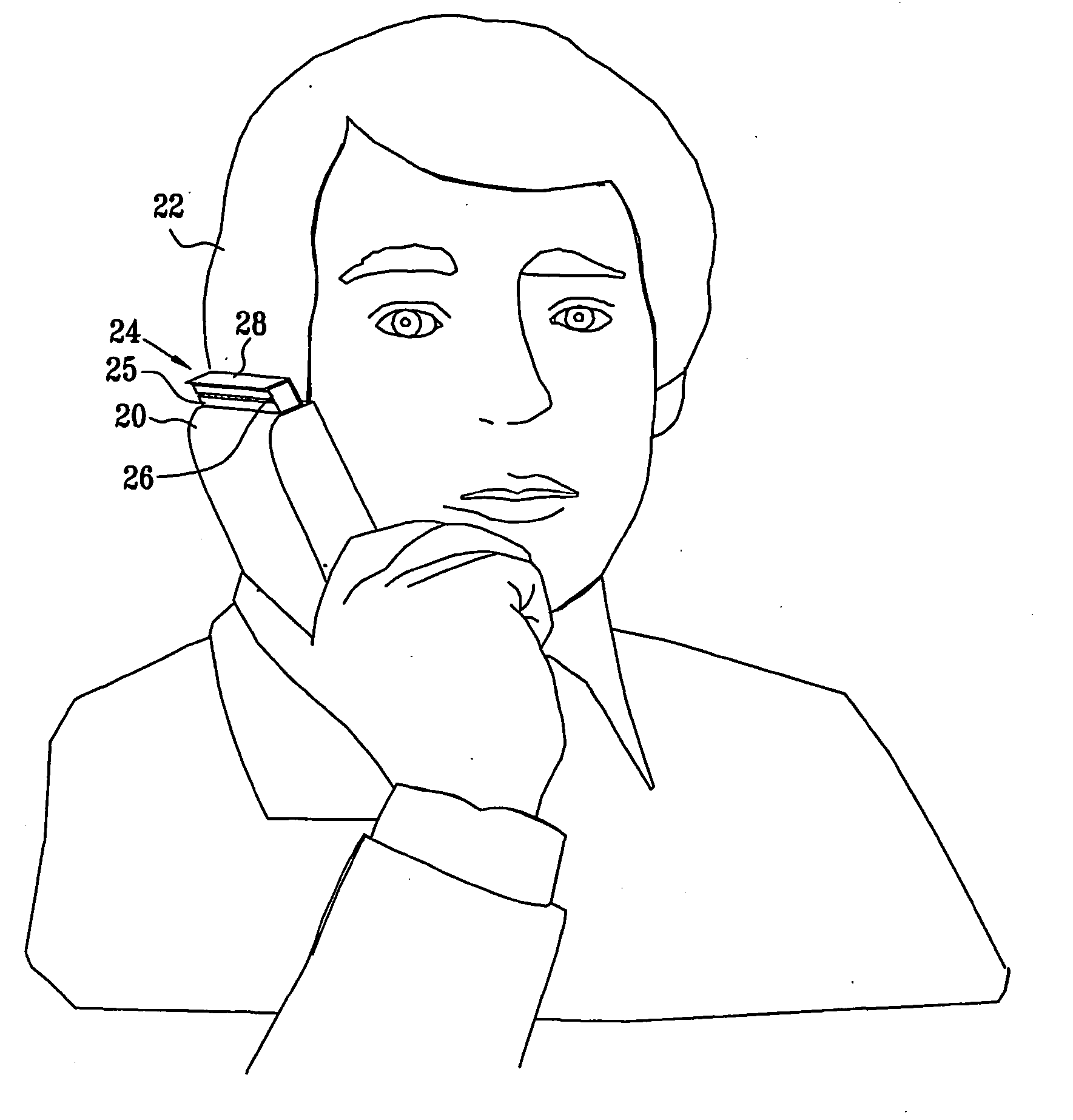
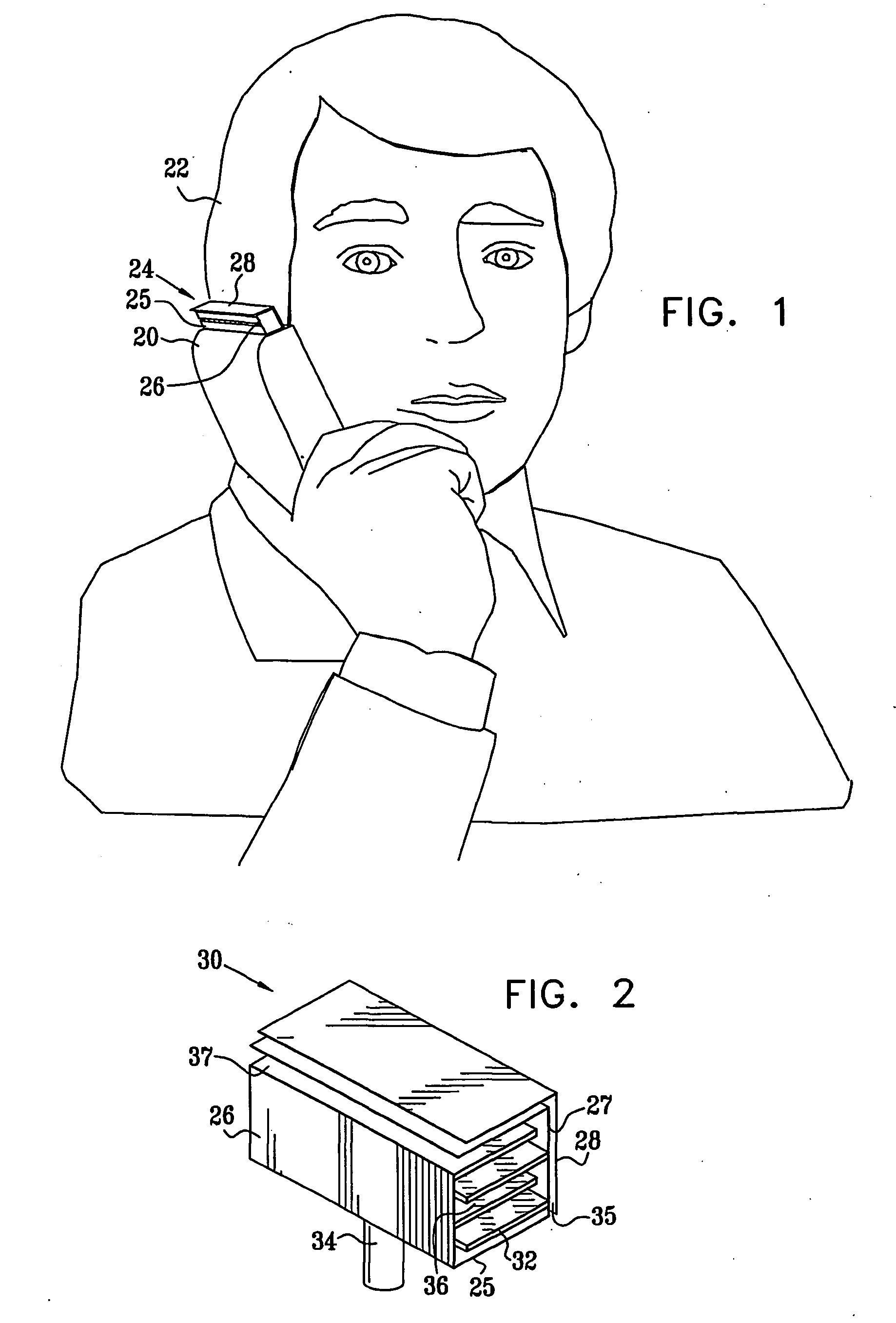
[0050]FIG. 1 is a schematic, pictorial illustration showing a cellular telephone 20 held next to a head 22 of a user, in accordance with a preferred embodiment of the present invention. Telephone 20 comprises an antenna assembly 24, made up of a feed structure 25 and an electrically-reactive shielding surface 28. Feed structure 25 has a front surface 26 and a rear surface, not seen in this figure. Here and in the description that follows, the “front surface” of the feed structure (or the antenna assembly) refers to the side of the assembly that is generally pointed away from head 22, as shown in the figure, while the “rear surface” faces toward the head. The rear surface of feed structure 25, which is typically conductive, and reactive surface 28 together define an asymmetrical cavity therebetween. Various realizations of the feed structure and the asymmetrical cavity are shown in detail in the figures that follow.

[0051] The combination of the asymmetrical cavity and the feed struc...


PUM


Abstract

An antenna assembly (30) for a communication device (20) includes a feed structure (25), which has front and rear sides (26, 27), and which is coupled to be driven by the device so as to radiate an electromagnetic field in a given frequency band. An electrically reactive surface (28) is positioned adjacent to the rear side of the feed structure so as to define a cavity (35) between the feed structure and the reactive surface, thereby substantially nulling the electromagnetic field on the rear side of the feed structure.

Description

CROSS-REFERENCE TO RELATED APPLICATIONS [0001] This application claims the benefit of U.S. Provisional Patent Application No. 60 / 255,570, filed Dec. 14, 2000, and U.S. Provisional Patent Application No. 60 / 303,923, filed Jul. 6, 2001. It is related to a PCT patent application entitled, “Antenna with Virtual Magnetic Wall,” filed Dec. 6, 2001. All of these related applications are assigned to the assignee of the present patent application, and their disclosures are incorporated herein by reference.FIELD OF THE INVENTION [0002] The present invention relates generally to antennas, and specifically to devices and methods for controlling the Specific Absorption Rate (SAR) of radiation from the antenna of a mobile communication device in the tissues of a user of the device. BACKGROUND OF THE INVENTION [0003] Concern has been growing over the radiation hazard involved in use of cellular telephones. Complaints of headaches, dizziness and fatigue are common among heavy users of cellular phon...

Claims


Application Information

Patent Timeline
IPC IPC(8): H01Q1/24H01Q1/38H01Q3/44H01Q9/40H01Q13/08H01Q13/20H01Q15/00H01Q15/22H04M1/02
CPCH01Q1/242H01Q1/245H01Q1/38H01Q13/08H01Q15/0013H01Q13/20H01Q15/22H01Q19/062H01Q13/10H01Q1/24
Inventor PELED, ASHERHEYMAN, EHUDSTEINBERG, BEN-ZIONKASTNER, RAPHAELBOAG, AMIR
Owner XELLANT
Why Eureka
Try Eureka