Phase-locked loop structures with enhanced signal stability

Active Publication Date: 2005-05-19
ANALOG DEVICES INC +1
View PDF14 Cites 16 Cited by
  • Summary
  • Abstract
  • Description
  • Claims
  • Application Information

AI Technical Summary

Benefits of technology

[0009] The present invention is directed to phase-locked loop struc

Problems solved by technology

Accordingly, conventional phase-locked loop structures generally compromise signal stability because they increase the oscillator gain sufficiently to insure that, under all operating and process variations, the

Method used


Image

  • Phase-locked loop structures with enhanced signal stability
  • Phase-locked loop structures with enhanced signal stability
  • Phase-locked loop structures with enhanced signal stability

Examples


Example

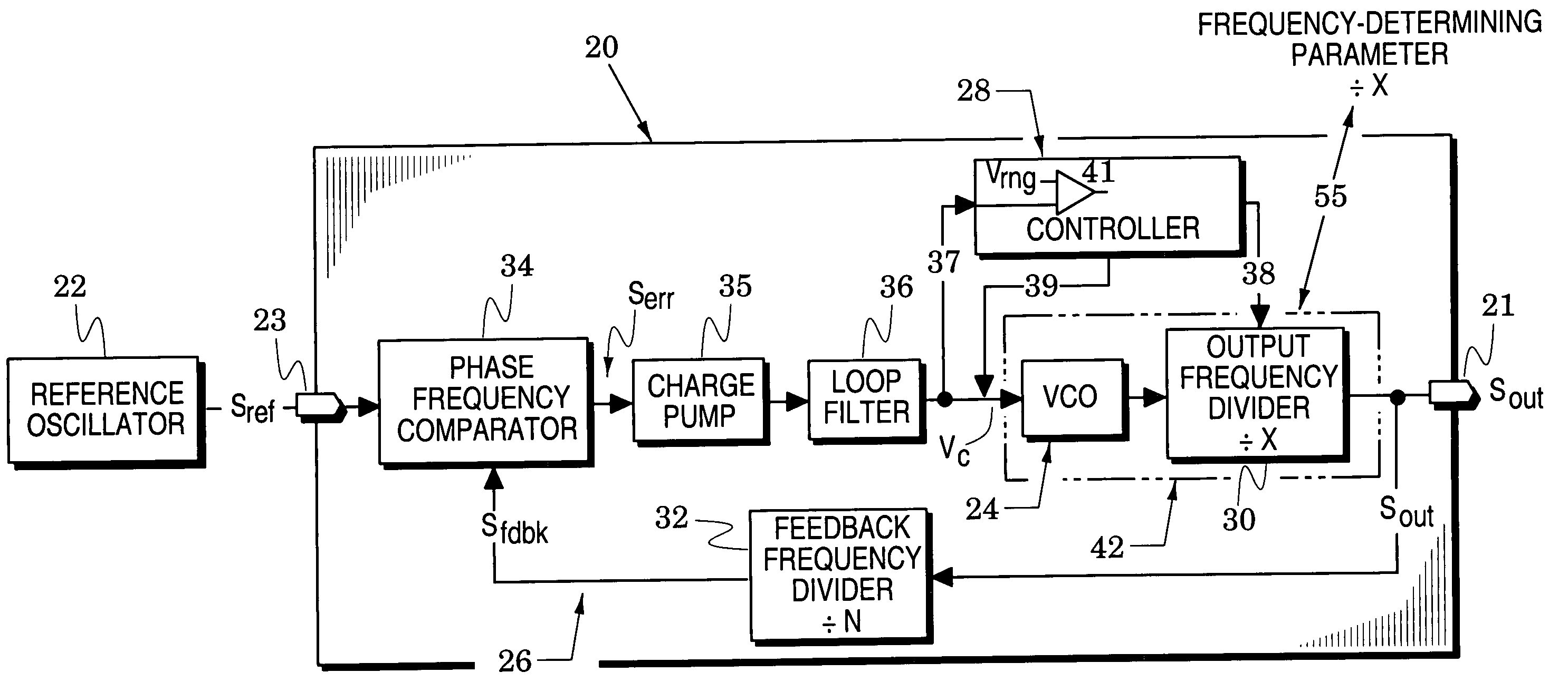
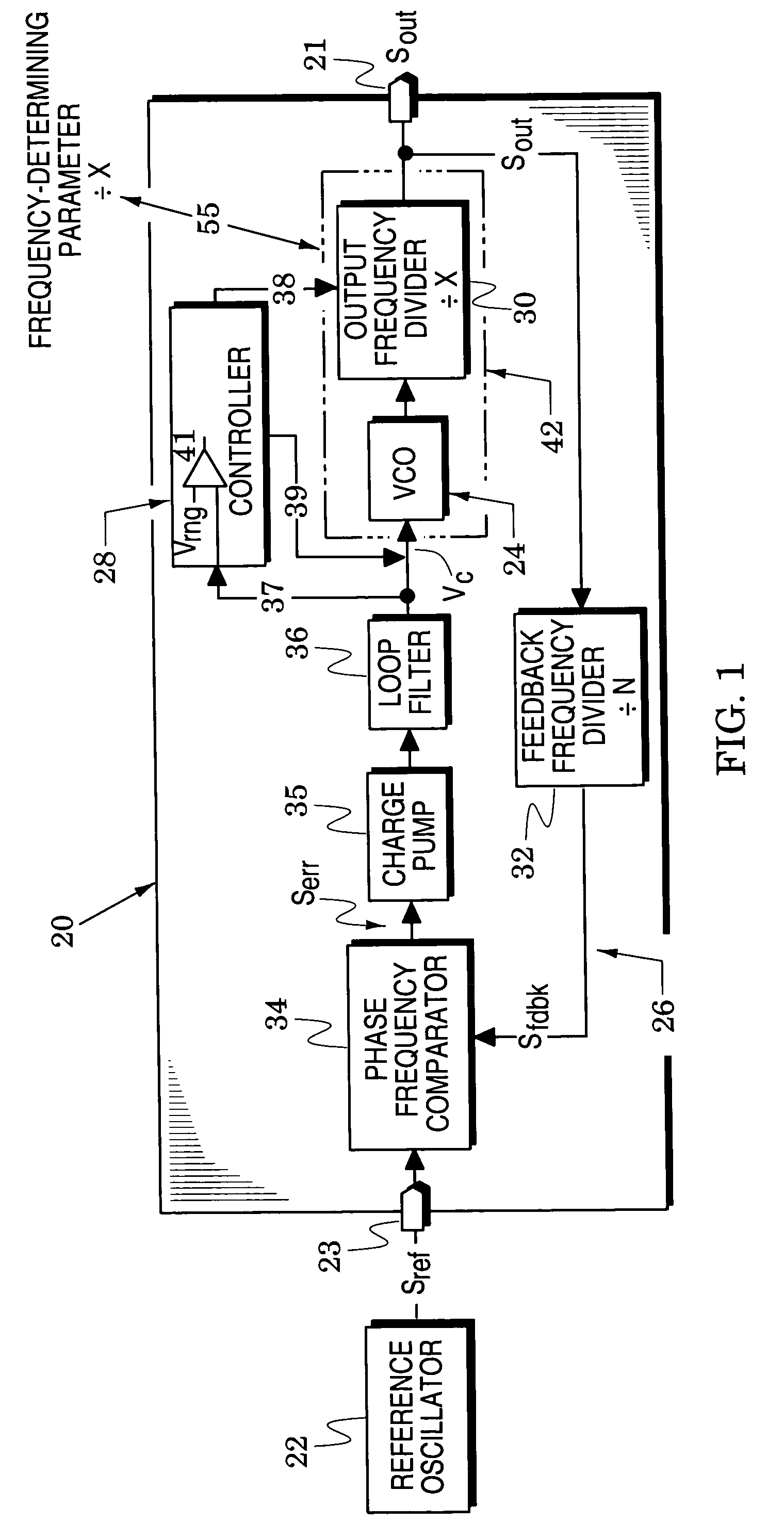
[0019] Phase-locked loop structures of the invention facilitate the use of low-gain oscillator circuits to thereby enhance signal stability. These structures operate in a closed-loop state (i.e., they do not require opening of the loop) which simplifies and shortens loop operations. Structural embodiments of FIGS. 1 and 4 and operational processes of FIGS. 2 and 4 are described below in detail.

[0020] In particular, FIG. 1 illustrates a phase-locked loop system 20 that provides a loop output signal Sout at an output port 21 in response to the reference signal Sref of a reference oscillator 22 at an input port 23. The system 20 includes a voltage-controlled oscillator (VCO) 24, a feedback loop 26 and a controller 28. The VCO 24 generates an oscillator signal Sosc whose frequency varies in response to a control voltage Vc and the feedback loop 26 generates the control voltage Vc in response to the phase difference between the reference signal Sref and a loop feedback signal Sfdbk. The...


PUM


Abstract

Phase-locked loop structures are provided that facilitate enhanced stability of loop-generated signals. They include an oscillator network, a feedback loop and a controller. The oscillator network generates a loop output signal with a frequency that varies in response to a control voltage and to a frequency-determining parameter, the feedback loop generates the control voltage in response to the loop output signal and a reference signal and the controller increments the frequency-determining parameter to maintain the control voltage within a predetermined control-voltage range. These structures enhance signal stability by facilitating the use of low-gain oscillator structures and they simplify and shorten loop operations because the structures operate in a closed-loop condition at all times.

Description

BACKGROUND OF THE INVENTION [0001] 1. Field of the Invention [0002] The present invention relates generally to phase-locked loop structures. [0003] 2. Description of the Related Art [0004] Phase-locked loop structures are used in a wide variety of modern electronic systems (e.g., signal-conditioning systems, signal-generating systems and communication systems) that require stable signals whose frequencies can be easily selected (i.e., synthesized) and whose close-in spectrum approximates that of a stable reference oscillator (e.g., a crystal oscillator). [0005] The phase-locked loop of these structures is generally completed around a voltage-controlled oscillator that generates an oscillator signal whose oscillator frequency varies in response to a control voltage. The frequency of this oscillator can be substantially greater than that of the reference oscillator and yet its close-in jitter (signal instability) will be controlled by the feedback loop to be a function of the low jitt...

Claims


Application Information

Patent Timeline
IPC IPC(8): H03L7/099H03L7/10H03L7/18
CPCH03L7/0992H03L7/0996H03L7/18H03L7/10H03L7/0997H03L7/113
Inventor MILLER, RODNEY DEANDINIZ, GEORGE F.STROUD, ERNEST T.
Owner ANALOG DEVICES INC
Why Eureka
Try Eureka