Simultaneous development of underground caverns and deposition of materials

Active Publication Date: 2005-05-19
MPEH LLC
View PDF20 Cites 26 Cited by
  • Summary
  • Abstract
  • Description
  • Claims
  • Application Information

AI Technical Summary

Benefits of technology

[0013] The method of this invention centers around the innovative concept of depositing wastes or other materials in salt caverns while simultaneously creating the caverns by a solution mining technique carried out under controlled conditions. The method comprises drilling a well into a naturally occurring salt formation and initiating the development of a salt cavern by means of solution mining techniques so as to mine the formation of salt with water (seawater or fresh water). When the initial development of the salt cavern in this fashion has been carried out to an extent sufficient to accommodate the injection of a prescribed amount of such wastes or other materials into the cavern, injection of the wastes or other materials through the well is started while continuing to develop the cavern by solution mining techniques. The injection of the wastes or other materials may be carried out continuously (into the constant flow of solution mining water), or intermittently (at time intervals between successive injections of solution mining water). The proportion and rates of wastes or other materials and solution mining water injected into the well are monitored and regulated so that cavern development continues in a manner and at a rate that allows the cavern to reach an intended prescribed size while the wastes or other materials are injected and deposited into the cavern. A casing is provided with the well, and adjustable hanging pipe strings are positioned within the casing in order to allow the injecti

Problems solved by technology

While the technologies described in these patents serve to address a number of individual waste disposal situations, none of them addresses the dual task of developing and/or enlarging a salt cavern whi

Method used


Image

  • Simultaneous development of underground caverns and deposition of materials
  • Simultaneous development of underground caverns and deposition of materials
  • Simultaneous development of underground caverns and deposition of materials

Examples


Example

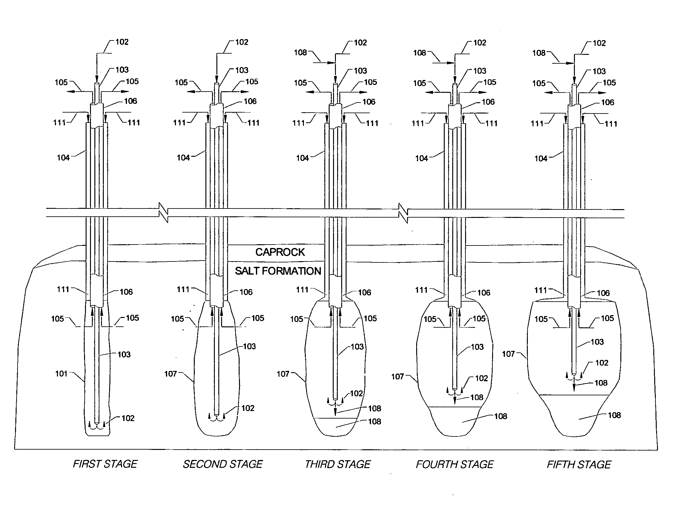
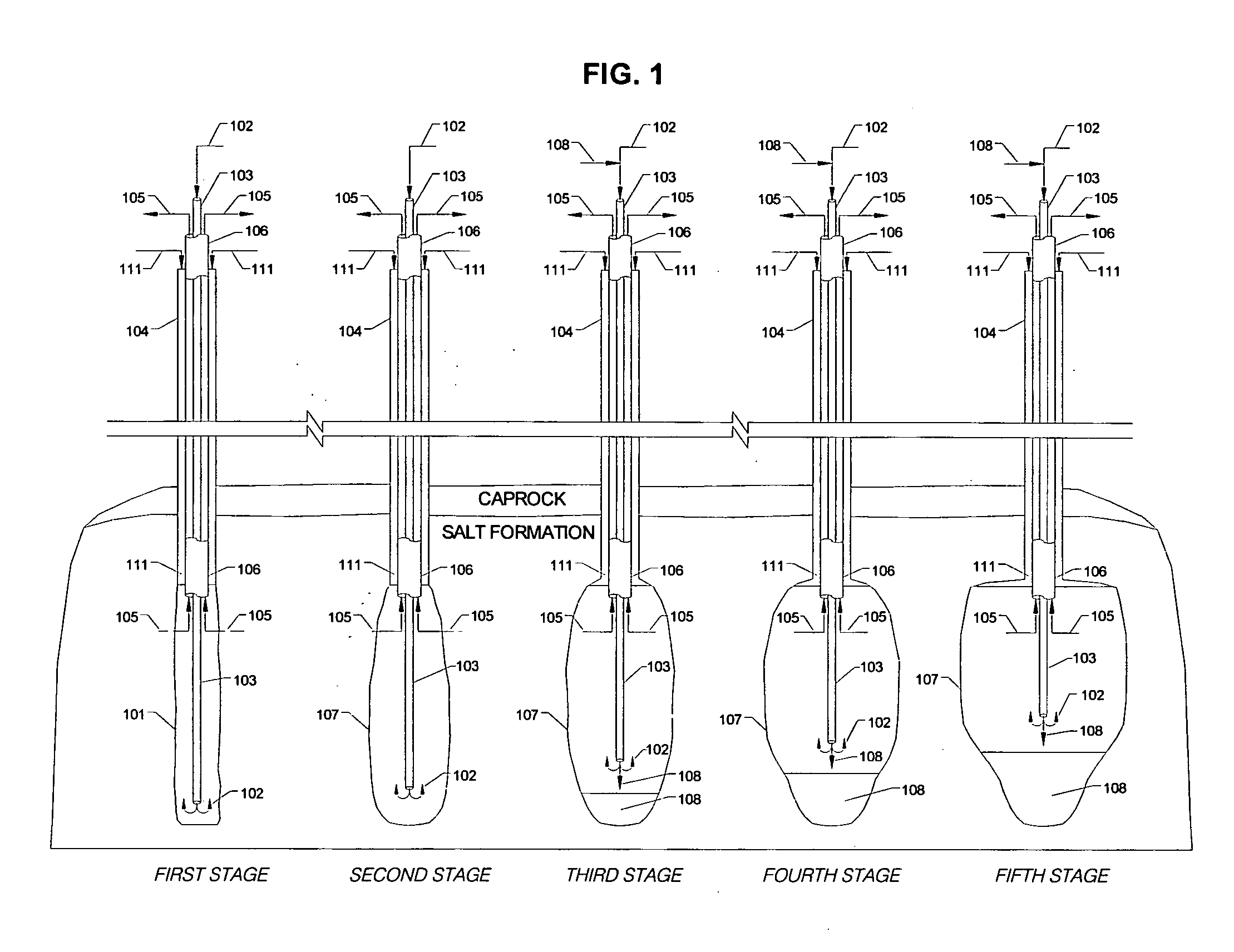
[0015] In FIG. 1 the method of this invention is illustrated in time sequence fashion with reference to the creation and development of a subterranean salt cavern and the simultaneous disposal of a heavier-than-brine solid waste. Referring to FIG. 1, a well 101 is first drilled into a naturally occurring salt formation located, typically, between about 500 and 3,000 feet below the surface of the earth. The initial drilling of the well is depicted in the First Stage diagram of FIG. 1, where well 101 is shown equipped with casing 104, which contains hanging mining pipe strings. Seawater 102 is injected through pipe 103, set inside casing 104 as part of the hanging pipe strings, and used to leach the salt in the salt formation. Pipe 103 is preferably made of steel, but it may also be made of other alloys, fiberglass or other materials. Since salt tends to dissolve in water up to 26% by weight, the leaching of the salt results in the extraction of brine 105, which exits through brine pi...


PUM


Abstract

A method is provided for simultaneously developing caverns while depositing wastes or other materials in them. A well is first drilled into a salt formation and the development of a salt cavern by means of solution mining is initiated. When the development of the cavern has been carried out to an extent sufficient to accommodate the injection of a prescribed amount of wastes or other materials, injection of the wastes or other materials through the well is started while continuing to develop the cavern by solution mining. The injection of the wastes or other materials may be carried out continuously or intermittently. The proportion and rates of wastes or other materials and mining water injected into the well are monitored and regulated so that cavern development continues at a rate that allows the cavern to reach an intended prescribed size while the wastes or other materials are injected and deposited into the cavern.

Description

[0001] This application is a non-provisional application for patent entitled to a filing date and claiming the benefit of earlier-filed Provisional Application for Patent No. 60 / 519,256, filed on Nov. 13, 2003 under 37 CFR 1.53 (c).FIELD OF THE INVENTION [0002] This invention relates to a method for the deposition of materials and the disposal of wastes. Particularly, this invention relates to a method for the disposal of wastes generated in the natural resource mining industry. More particularly, the invention relates to a method for the deposition of materials and the disposal of wastes in underground reservoirs. Specifically, the invention relates to a novel technique for creating and providing underground caverns by means of solution mining techniques while simultaneously disposing of wastes in said underground caverns. BACKGROUND OF THE INVENTION [0003] The constant increase in waste generation worldwide is accompanied by an increasing need to provide for proper waste disposal....

Claims


Application Information

Patent Timeline
IPC IPC(8): E21B43/28
CPCE21B43/28
Inventor MADUELL, ROGER JACQUESLANDRY, DAVID CHARLESSINGLETON, DAVID BRIAN
Owner MPEH LLC
Why Eureka
Try Eureka