High flow rate fuel valve and fuel supply pump with the valve

a high flow rate, fuel valve technology, applied in the direction of pump control, fuel injection apparatus, charge feed system, etc., can solve the problems of large amount of fuel not being pressurized sufficiently, complex accumulation fuel injection device, etc., to achieve easy pressurization, easy to prevent generation of erosion, and easy to raise combustion efficiency in the fuel injection system

Inactive Publication Date: 2005-05-19
DIESEL KIKI CO LTD
View PDF6 Cites 12 Cited by
  • Summary
  • Abstract
  • Description
  • Claims
  • Application Information

AI Technical Summary

Benefits of technology

[0027] Using such an accumulator fuel injection device, a large amount of fuel can be easily pressurized. Therefore, the combustion efficiency in the fuel injection system can be raised. Also, the generation of erosion can be easily prevented, while the durability can be increased.

Problems solved by technology

Therefore, there is a problem in that the accumulator fuel injection device is complicated and grown in size.
In the accumulator fuel injection device, furthermore, there is an another problem in that a large amount of fuel cannot be pressurized sufficiently because the fuel is difficult to flow quickly to the fuel injection valve when the cam and plunger of the fuel supply pump are driven at high speed.
As the flow rate of fuel is restricted, a large amount of fuel cannot be pressurized sufficiently.
Any fuel injection valve adapted for the pressure pump, which intends to supply a large amount of high-pressure fuel, is not designed.
Furthermore, the fuel injection valves disclosed in JP 06-101597 A and JP 10-47208 A are difficult to be used as high flow fuel valves because their structures differ fundamentally from the high flow fuel valves in that the proportion of the length of an injection hole to the diameter of the injection hole is restricted within a predetermined range, a revolving body is installed, and so on.

Method used


Image

  • High flow rate fuel valve and fuel supply pump with the valve
  • High flow rate fuel valve and fuel supply pump with the valve
  • High flow rate fuel valve and fuel supply pump with the valve

Examples


first embodiment

[0052] As illustrated in (a) and (b) of FIG. 1, a first embodiment of the present invention is a high flow fuel valve 73 that comprises a valve main body 19, a valve body 20 movably installed in the inside of the valve main body 19, an inlet chamber 19a formed in the inside of the valve main body 19, inlet holes 19c, and a seat portion 23 where part of the valve body 20 and part of the valve main body 19 are contact with each other. The high flow fuel valve 73 is characterized in that a plurality of inlet holes 19c is formed and these inlet holes 19c are arranged in a non-radical pattern relative to the inlet chamber 19a.

[0053] Hereinafter, the high flow fuel valve 73 will be described more concretely by way of individually describing its structural components.

1. Valve Main Body

[0054] A valve main body is not specifically limited to a certain configuration as far as it retains a valve body and performs a predetermined movement. Preferably, however, the valve main body may be in ...

second embodiment

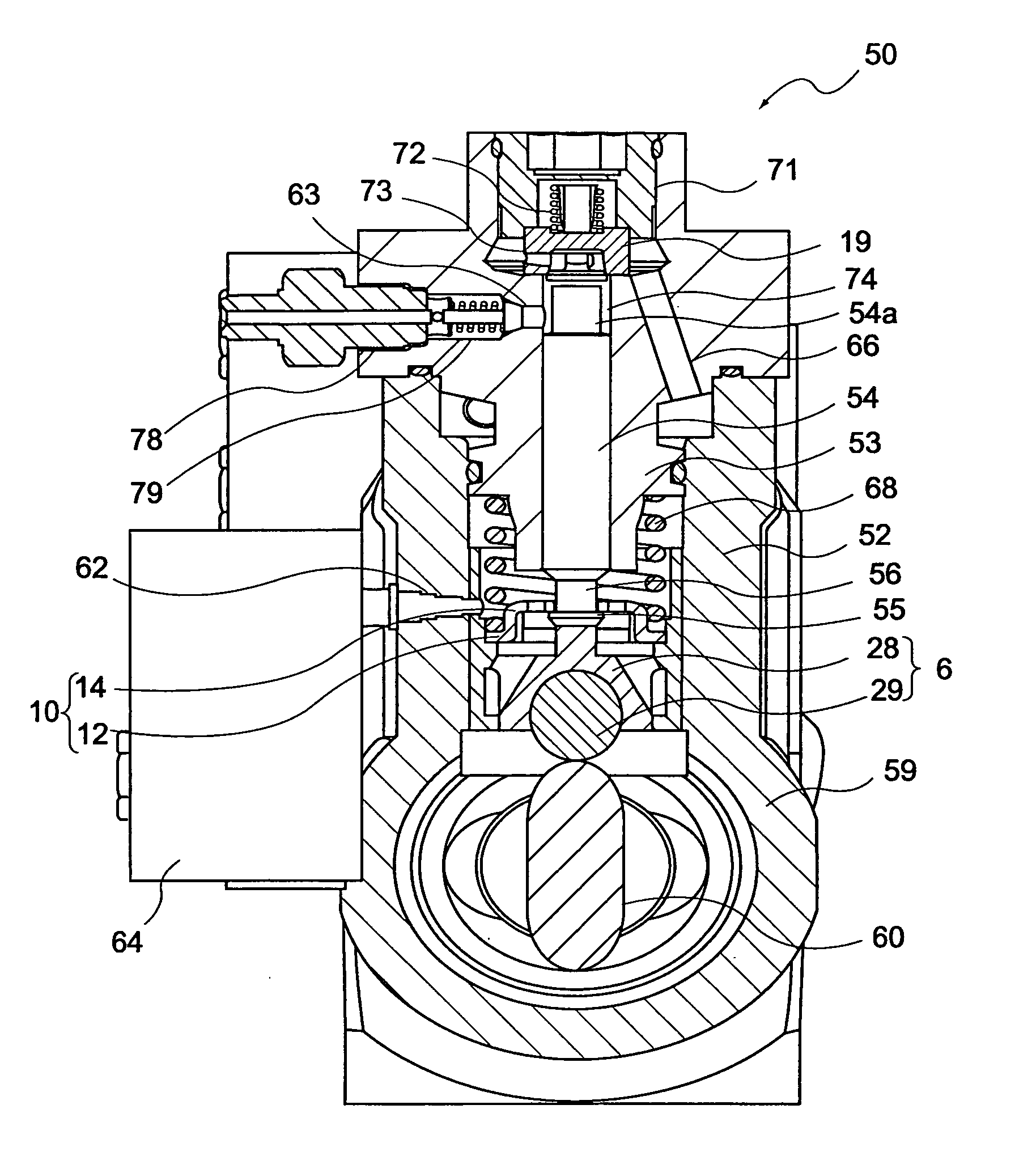
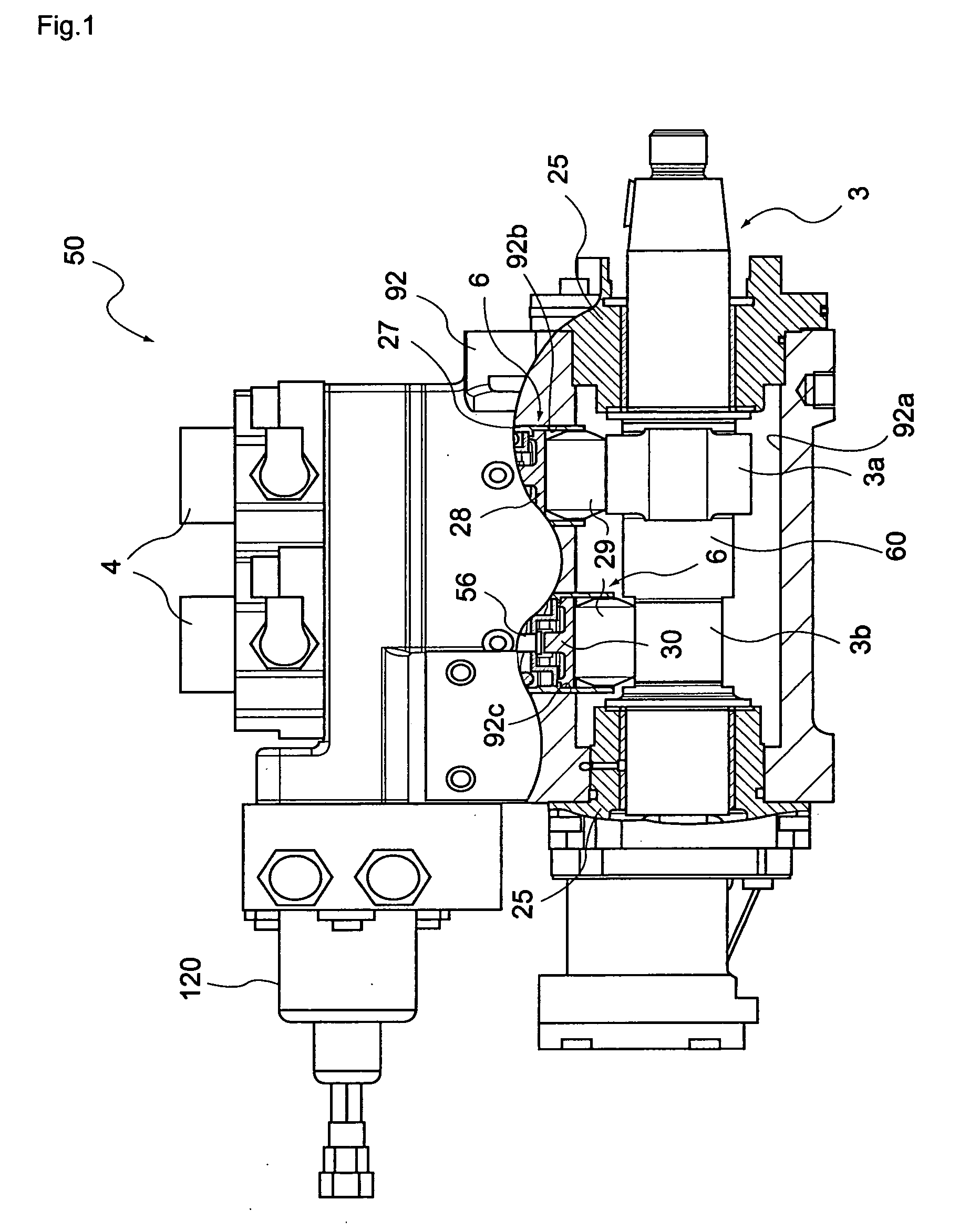
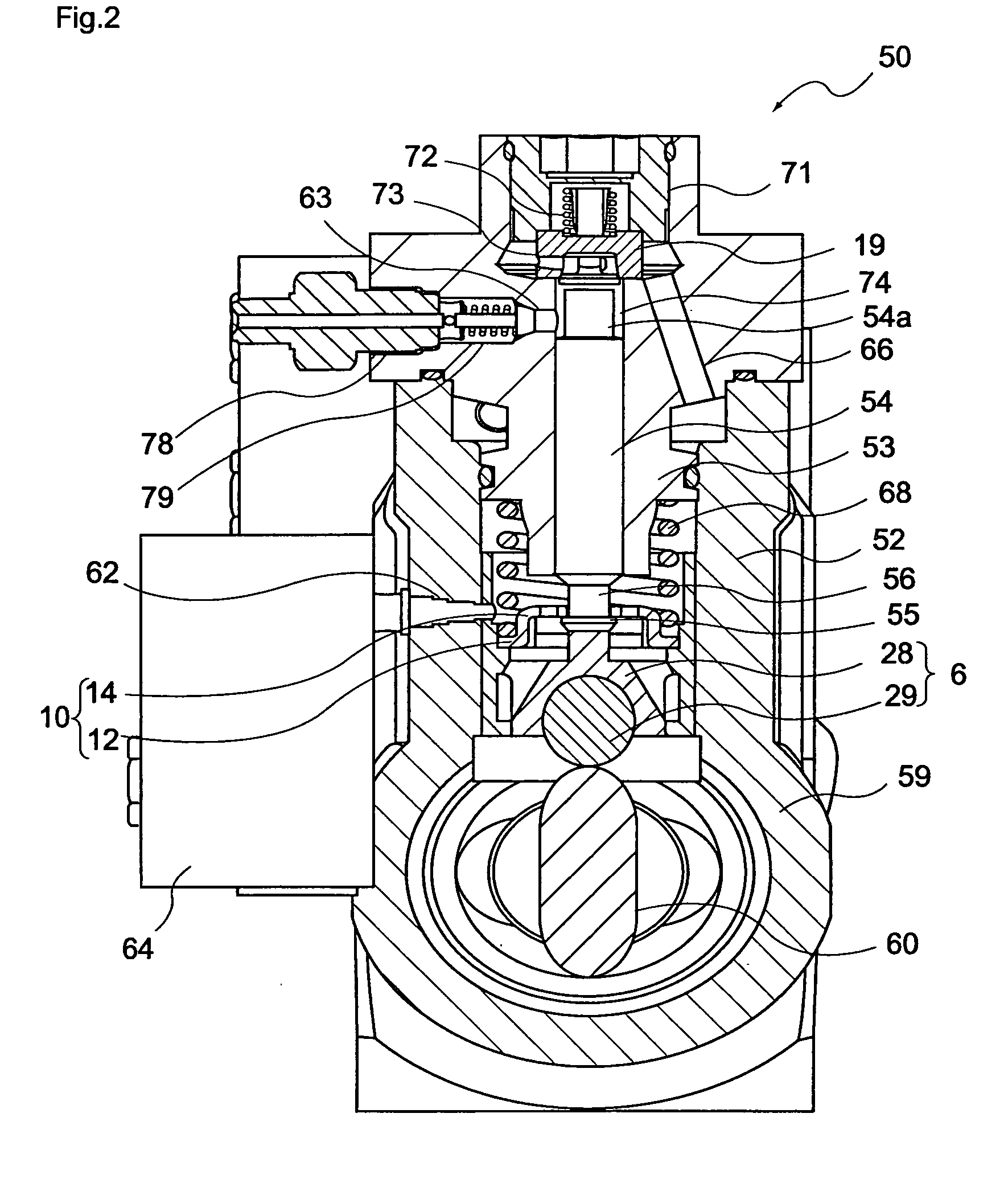
[0102] As shown in FIG. 13, a second embodiment of the present invention is a fuel supply pump 50 having a fuel inlet valve 73 and a fuel outlet valve 19 and is characterized by the following configuration. The fuel inlet valve 73 comprises a valve main body 19, a valve body 20 movably installed in the inside of the valve main body 19, an inlet chamber 19a formed in the inside of the valve main body 19, inlet holes 19c, a seat portion 23 where part of the valve body 20 and part of the valve main body 19 are contact with each other, wherein a plurality of inlet holes 19c is formed and these inlet holes 19c are arranged in a non-radical pattern.

[0103] Hereinafter, the fuel supply pump 50 will be described more concretely by way of individually describing its structural components.

1. Fuel Inlet Valve

[0104] The second embodiment is characterized in that a fuel inlet valve used is the high flow fuel valve described in the first embodiment. Thus, it is preferable to design an IO valve...


PUM


Abstract

A high flow rate fuel valve suitable for an accumulator fuel injection device by which a large amount of fuel is amplified using a piston and used and a fuel supply pump using the high flow rate fuel valve are provided. For this purpose, in a fuel supply pump with a fuel inlet valve and fuel outlet valve, the fuel inlet valve has a valve main body, a valve body received in the valve main body, an inlet chamber provided inside the valve main body, inlet holes, a seat portion where the valve body and part of valve main body are in contact with each other. The inlet holes are arranged in a non-radial pattern relative to the inlet chamber.

Description

TECHNICAL FIELD [0001] The present invention relates to a high flow rate fuel valve and a fuel supply pump with the valve. Particularly, the present invention relates to a high flow rate fuel valve suitable for a fuel supply pump used in an accumulator fuel injection device (APCRS: Amplified Piston Common Rail System) that amplifies the pressure of a large flow rate of fuel through the use of a pressure piston, and a fuel supply pump with the valve. BACKGROUNDS [0002] Conventionally, various accumulator fuel injection devices (CRSs: Common Rail Systems) using pressure accumulators (common rails) have been proposed in order to inject high-pressure fuels efficiently in diesel engines and so on. [0003] For instance, as shown in FIG. 20, for switching the pressures of a pressure accumulator depending on the driving conditions of an engine, JP 06-93936 A has proposed an accumulator fuel injection device having a first pressure accumulator 236 responsible for a main injection and a second...

Claims


Application Information

Patent Timeline
Patent Type & Authority Applications(United States)
IPC IPC(8): F02M45/00F02M47/02F02M57/02F02M59/10F02M59/36F02M59/46F02M63/02
CPCF02M45/00F02M47/027F02M63/0225F02M59/105F02M59/464F02M57/025
Inventor AOKI, NOBUOKUBOTA, KAZUYATERADA, TAKESHIICHINOSE, TAKESHI
Owner DIESEL KIKI CO LTD
Why Eureka
Try Eureka