Hermetic compressor

Inactive Publication Date: 2005-05-19
LG ELECTRONICS INC
View PDF13 Cites 39 Cited by
  • Summary
  • Abstract
  • Description
  • Claims
  • Application Information

AI Technical Summary

Benefits of technology

[0022] Accordingly, the present invention is directed to a hermetic compressor that substantial

Problems solved by technology

However, the related art hermetic compressor has the following problems.
Second, if the coil weight is not fitted accurately, the loop pipe and the coil

Method used


Image

  • Hermetic compressor
  • Hermetic compressor
  • Hermetic compressor

Examples


Embodiment Construction

[0042] Reference will now be made in detail to the preferred embodiments of the present invention, examples of which are illustrated in the accompanying drawings. In describing the embodiments, same parts will be given the same names and reference symbols, and repetitive description of which will be omitted.

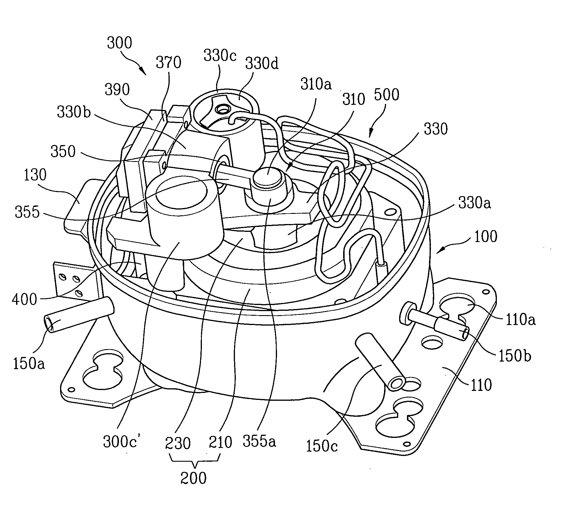
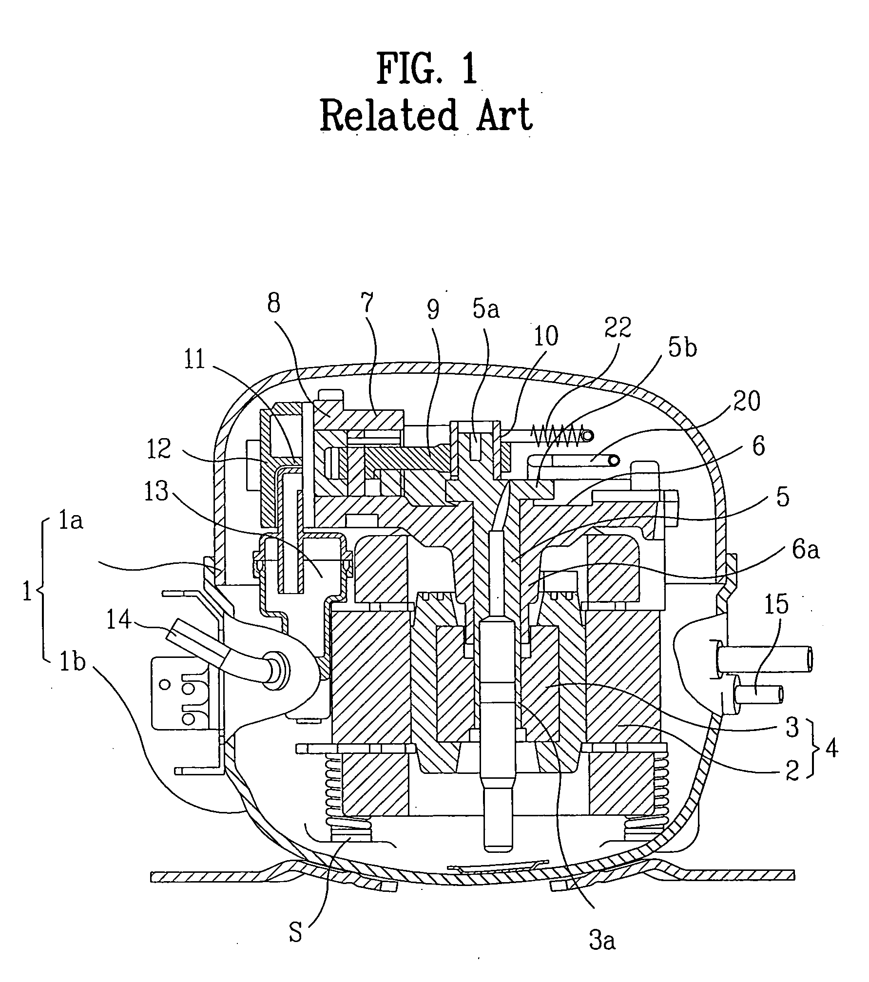
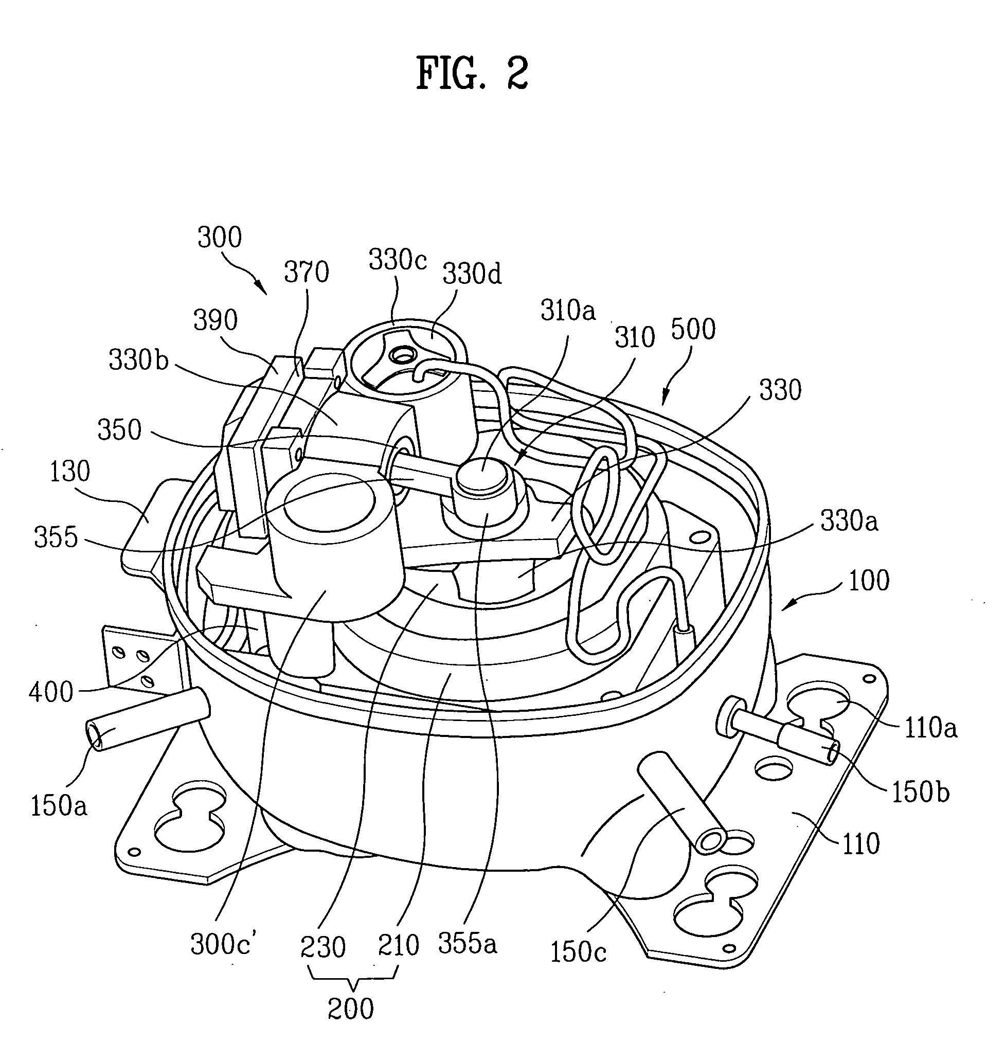
[0043] Respective embodiments of the hermetic compressor of the present invention will be described with reference to FIGS. 2˜4. FIG. 2 illustrates a disassembled perspective view of a hermetic compressor of the present invention.

[0044] Referring to FIG. 2, on an outside of the hermetic compressor, there are an oval lower container 100 having a downward hollow space, and an upper container (not shown) having an upward hollow space for covering a top of the lower container 100.

[0045] There are supporting parts 110 on opposite side parts of an underside of the lower container 100. There is a rubber seat (not shown) between the supporting parts 110 and a floor of a room for absor...


PUM


Abstract

Hermetic compressor including a hermetic container having an enclosed space therein, a motor part in the hermetic container for converting an electric energy into a kinetic energy, a compression part connected to the motor part for compressing low temperature, low pressure refrigerant into high temperature, high pressure refrigerant, a discharge muffler adjacent to the compression part for attenuating noise of the refrigerant compressed into high temperature and high pressure, a discharge pipe passed through one side of the hermetic container for discharging the refrigerant to an outside of the compressor, and a loop pie of a synthetic resin between the discharge muffler and the discharge pipe.

Description

[0001] This application claims the benefit of the Korean Application No. P2003-080528, filed on Nov. 14, 2003, which is hereby incorporated by reference. BACKGROUND OF THE INVENTION [0002] 1. Field of the Invention [0003] The present invention relates to compressors, and more particularly, to a hermetic compressor. [0004] 2. Background of the Related Art [0005] In general, the hermetic compressor compresses low temperature, low pressure gaseous refrigerant into high temperature, high pressure gaseous refrigerant in a refrigerating system. The hermetic compressor is provided with a compression part for compressing the refrigerant, a motor part for supplying power to the compression part, and a hermetic container for holding the compression part and the motor part. The refrigerant is compressed by a piston reciprocating within a cylinder. [0006]FIG. 1 illustrates a section of a related art hermetic compressor. [0007] Referring to FIG. 1, the hermetic compressor is provided with a cont...

Claims


Application Information

Patent Timeline
IPC IPC(8): F04B39/00F04B39/12F04C23/00F04C29/06
CPCF04B39/0055F04B39/0061F04C29/068F04C23/008F04C29/065F04B39/123F04B39/00
Inventor KIM, TAE MINLEE, HYO JAE
Owner LG ELECTRONICS INC
Why Eureka
Try Eureka