Fuel cell having stack structure
a fuel cell and stack technology, applied in the field of stack structure fuel cells, can solve the problems of non-uniform distribution of the wet state of the electrolyte membrane, non-uniform distribution of the electric power generation performance of the unit cell, etc., and achieve the effect of suppressing the electric power generation performance of the fuel cell and likely reducing the electric power generation performan
- Summary
- Abstract
- Description
- Claims
- Application Information
AI Technical Summary
Benefits of technology
Problems solved by technology
Method used
Image
Examples
first embodiment
[0051] the invention will be described.
[0052] First, configurations of the electrodes will be described.
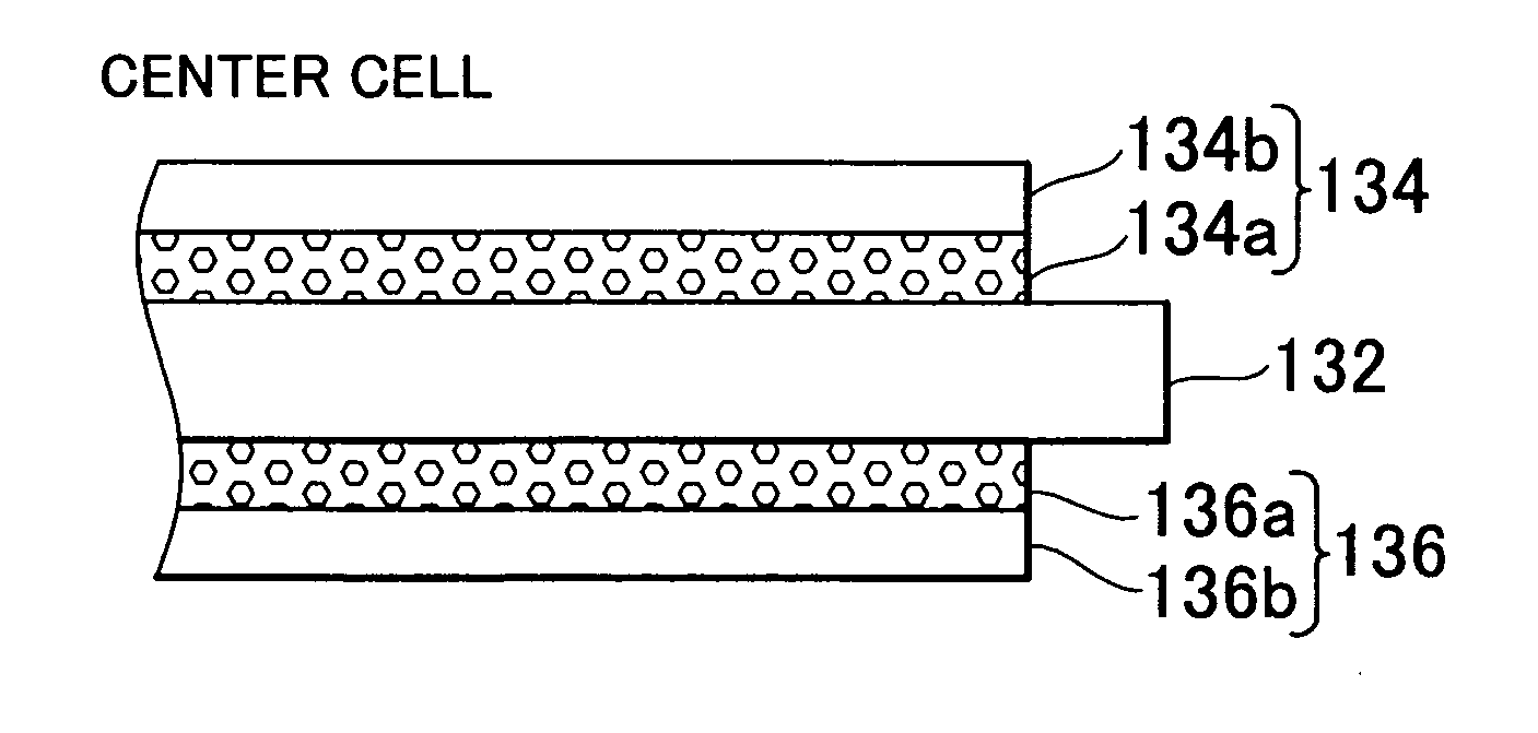
[0053]FIG. 3A is an explanatory diagram showing a configuration of the fuel cell stack 10 according to the first embodiment of the invention. FIG. 3B is a cross sectional view showing a configuration of an electrode of a unit cell positioned at the center portion of the fuel cell stack 10 (hereinafter, referred to as “center cell”). FIG. 3C is a cross sectional view showing a configuration of an electrode of a unit cell positioned at the end portion of the fuel cell stack 10 (hereinafter, referred to as “end portion cell”).
[0054] As shown in FIG. 3B, in the center cell, a catalyst layer 134a and a gas diffusion layer 134b are stacked in this order on one surface of the electrolyte membrane 132, whereby the hydrogen electrode 134 is formed. Also, a catalyst layer 136a and a gas diffusion layer 136b are stacked in this order in the other surface of the electrolyte membrane 132, wh...
second embodiment
[0064] Hereinafter, the invention will be described.
[0065] In the first embodiment, the thickness of each catalyst layer in the center cell is different from that in the end portion cell. In the second embodiment, the specific surface area of the catalyst supported by each catalyst layer in the center cell is different from that in the end portion cell.
[0066]FIG. 5A to FIG. 5C are explanatory diagrams showing configurations of electrodes of the unit cells 100 according to a second embodiment of the invention. In the second embodiment, the thickness of each of the catalyst layers 134a and 136a in the center cell is the same as the thickness of each of the catalyst layers 134e and 136e in the end portion cell. The second embodiment is the same as the first embodiment, except that the specific surface area of the catalyst supported by each of the catalyst layers 134e and 136e in the end portion cell is larger than that of the catalyst supported by each of the catalyst layers 134a and ...
PUM
 Abstract
Description
Claims
Application Information
 - R&D
- Intellectual Property
- Life Sciences
- Materials
- Tech Scout
- Unparalleled Data Quality
- Higher Quality Content
- 60% Fewer Hallucinations
Browse by: Latest US Patents, China's latest patents, Technical Efficacy Thesaurus, Application Domain, Technology Topic, Popular Technical Reports.
© 2025 PatSnap. All rights reserved.Legal|Privacy policy|Modern Slavery Act Transparency Statement|Sitemap|About US| Contact US: help@patsnap.com


