
Toner kit, deep-color cyan toner, pale-color cyan toner, and image forming method

a toner kit and kit technology, applied in the field of toner kits, can solve the problems of gradation of toner images, inability to accurately place toner particles on each dot, and inability to accurately place toner particles, so as to reduce graininess or roughness and improve quality

Inactive Publication Date: 2005-05-19
CANON KK
View PDF6 Cites 26 Cited by
  • Summary
  • Abstract
  • Description
  • Claims
  • Application Information

AI Technical Summary

Benefits of technology

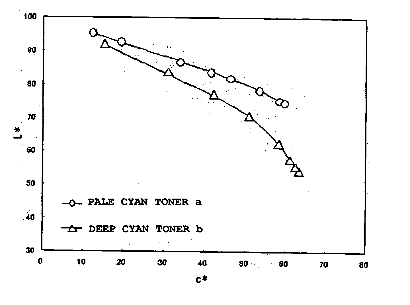
[0012] An object of the present invention is to solve the above-mentioned problems in the conventional art. In other words, it is an object of the present invention to provide: a toner kit having deep and pale cyan toners, which is capable of at least forming an image having a higher quality by decreasing the graininess or roughness from the low density area to the high density area; and a method of forming an image using the above deep and pale cyan toners.

Problems solved by technology

In this method, however, toner particles are hardly placed on each dot with precision, so that the toner particles may lie off the dot.
Therefore, a problem is likely to occur in that the gradation of a toner image corresponding to the ratio of dot densities in black and white portions in a digital latent image.
In this method, however, it is difficult to reproduce the electric latent image formed from minute dots, resulting in a poor resolution.
Therefore, the resulting image tends to have particularly poor gradation in a highlight portion lacks in sharpness.
Furthermore, irregularities in an arrangement of dots cause graininess in the image, which leads to decrease in the image quality of the highlight portion.
In these documents, however, there is no teach or description about the amount or concentration of a colorant to be added in the toner and there is no teach or description about a favorable formulation of the toner.
According to the studies of the present inventors, it became evident that these image forming apparatuses had a problem of eminently increasing the graininess of an intermediate density area where the deep toner and the pale toner are mixed even though the gradation and the graininess of a low density area composed of only the pale toner are improved.
According to the studies of the present inventors, it became evident that the above image forming apparatuses had been designed insufficiently with respect to an extension of the range of color reproduction.

Method used


Image

  • Toner kit, deep-color cyan toner, pale-color cyan toner, and image forming method
  • Toner kit, deep-color cyan toner, pale-color cyan toner, and image forming method
  • Toner kit, deep-color cyan toner, pale-color cyan toner, and image forming method

Examples


manufacturing examples 2 to 12

of Cyan Toner

[0242] Cyan toners 2 to 12 were obtained in the same manner as in Cyan Toner Production Example 1 except that a mixing ratio of styrene and n-butyl acrylate was changed to change the Tg of the toner, the peak value of the molecular weight distribution was changed by using the addition amount of initiator, the weight average particle size of the toner was changed by using the addition amounts of aqueous solution of Na3PO4 and aqueous solution of CaCl2, and the addition amounts of colorant, charge control agent, and external additive were set to the values shown in Table 1. Tables 1 and 2 show the physical properties of the cyan toners 2 to 12 determined in the same manner as in the cyan toner 1.

examples 13

Manufacturing Examples 13 of Cyan Toner

[0243] (First Kneading Step)

Polyester resin (having an acid number of 7) obtained100 partsby subjectingby masspolyoxypropylene(2,2)-2,2-bis(4-hydroxyphenyl)propane,fumaric acid, and 1,2,5-hexanetricarboxylic acid tocondensation polymerizationFollowing compound (A) 0.7 partby mass

[0244] First, the above raw materials were loaded into a kneader-type mixer at the above prescription. The temperature in the mixer was increased to 130° C., and the mixture was melted and kneaded under heating for about 30 minutes to disperse the pigment. After that, the kneaded product was cooled and taken out as a first kneaded product.

[0245] (Second Kneading Step)

First kneaded product obtained in the above step100.7 parts by massAluminum compound of 3,5-di-t-butylsalicylate   2 parts by mass

[0246] Those materials were sufficiently premixed at the above prescription by using a Henschell mixer. The mixture was melted and kneaded by using a biaxial extruder set at...

manufacturing examples 14 to 18

of Cyan Toner

[0248] Cyan toners 14 to 18 were obtained in the same manner as in Cyan Toner Production Example 13 except that the addition amounts of colorant, charge control agent, and external additive were set to the values shown in Table 3. Tables 3 and 4 show the physical properties of the cyan toners 14 to 18.

TABLE 1AdditionAdditionAdditionamountsamountsPeak ofamountsof chargeofBET inWeightNumbermolec-ofcontrolexternalspecificaverageaverageularManufacturingcolorantagentagentsurfaceparticleparticleweightExamples ofDevel-(parts by(parts by(parts byareadiameterdiameterD4 / distri-TgtonerToneroperColorantmass)mass)mass)(m2 / g)D4 (μm)Dn (μm)Dnbution(° C.)Manu-ManufacturingCyanDevel-Pigment0.62.01.52.86.35.71.111320056fac-Example 1 ofToner 1oper 1Blue 16turingtonerEx-ManufacturingCyanDevel-Com-0.72.01.52.86.15.51.111330056amplesExample 2 ofToner 2oper 2pound (A)of PaletonerCyanManufacturingCyanDevel-Pigment0.52.01.52.86.45.51.161320056TonerExample 3 ofToner 3oper 3Blue 15:3tonerManufa...


PUM


Abstract

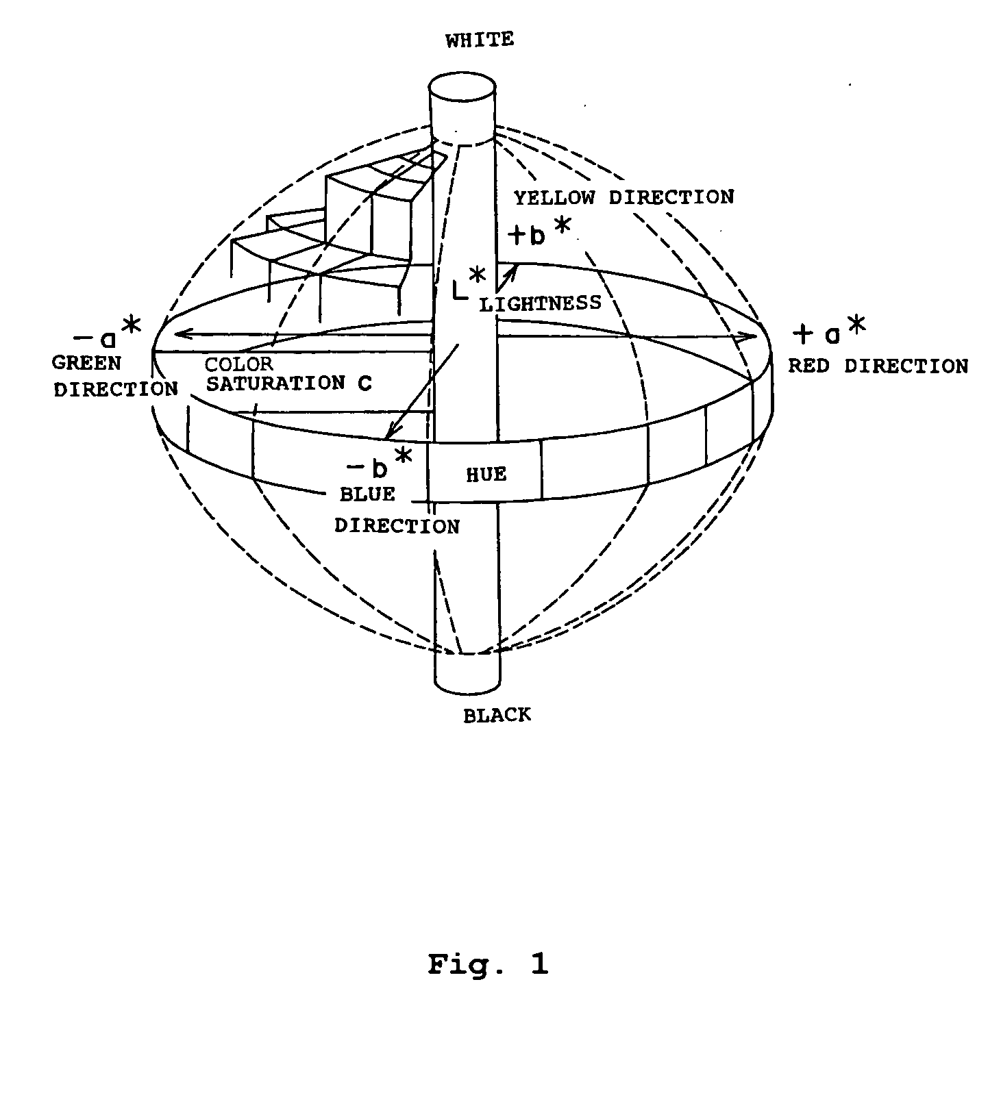
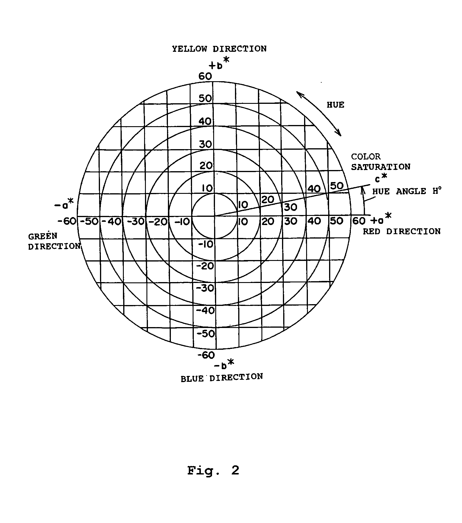
The present invention provides: a toner kit having a deep toner and a pale toner which are separated from each other, wherein: the deep toner and the pale toner satisfy prescribed conditions for an L*a*b* color coordinate system where a* represents a hue in the red-green direction, b* represents a hue in the yellow-blue direction, and L* represents a lightness; the pale toner and the deep toner to be used in the toner kit; and a method for forming an image using the toner kit. Thus, the present invention can form a high quality image, while suppressing graininess and roughness over the areas covering from the low density area to the high density area.

Description

BACKGROUND OF THE INVENTION [0001] 1. Field of the Invention [0002] The present invention relates to a toner kit for developing an electrostatic image or a toner kit for forming a toner image in accordance with a method for forming an image using a toner-jet system in a method for forming an image such as electrophotography or electrostatic printing. In particular, the present invention relates to a toner kit that comprises a toner to be used in a fixation system in which a toner image is fixed on a transfer material such as a print sheet under heat and pressure. Furthermore, the present invention relates to a method for forming an image of electrophotographic type method for forming an image to be used in a copying machine, a printer, a facsimile machine, a digital-proofing device, etc. and an image forming apparatus of electrophotographic type to which the method is applied. [0003] 2. Description of the Related Art [0004] Heretofore, various kinds of electrophotographic methods ha...

Claims


Application Information

Patent Timeline
Patent Type & Authority Applications(United States)
IPC IPC(8): G03G9/08G03G9/09G03G13/00G03G13/01G03G15/00G03G15/01G03G15/08G03G15/14
CPCG03G9/0821G03G9/0926G03G9/0906G03G9/09
Inventor AYAKI, YASUKAZUIKEDA, TAKESHIISHIDA, TOMOHITOITOH, NOBUYUKI
Owner CANON KK
Learn More