Device for stabilizing combustion in gas turbine engines

a gas turbine and combustion engine technology, applied in the direction of burner details, combustion types, lighting and heating apparatuses, etc., can solve the problems of low flux of hot and chemically reactive combustion products that are transported upstream, polluted emissions, nitrogen oxides,

Inactive Publication Date: 2005-05-19
SIEMENS AG
View PDF30 Cites 24 Cited by
  • Summary
  • Abstract
  • Description
  • Claims
  • Application Information

AI Technical Summary

Benefits of technology

[0022] The burner further includes a quarl device disposed adjacent to the downstream end portion of the main body. The quarl device defines an interior recirculation chamber and a burner exit. The interior recirc

Problems solved by technology

Several major technical problems are associated with the combustion process in gas turbine engines.
These problems include, for example, thermal efficiency of the burner/combustor, proper mixing of the fuel and air, flame stabilization, the elimination of pulsations and noise, and the control of polluting emissions, especially nitrogen oxides (NOx).
As a result, the flux of the hot and chemically reactive combustion products that are transported upstream is low and the combustion is less stable, especially when the combustion is lean.
However, in burners which use a quarl, when the swirl strength is strong, the flame has a tendency to move upstream, deep inside the burner causing damage to the burner components.
In addition to damaging the burner hardware, the uncontrolled

Method used


Image

  • Device for stabilizing combustion in gas turbine engines
  • Device for stabilizing combustion in gas turbine engines
  • Device for stabilizing combustion in gas turbine engines

Examples


Embodiment Construction

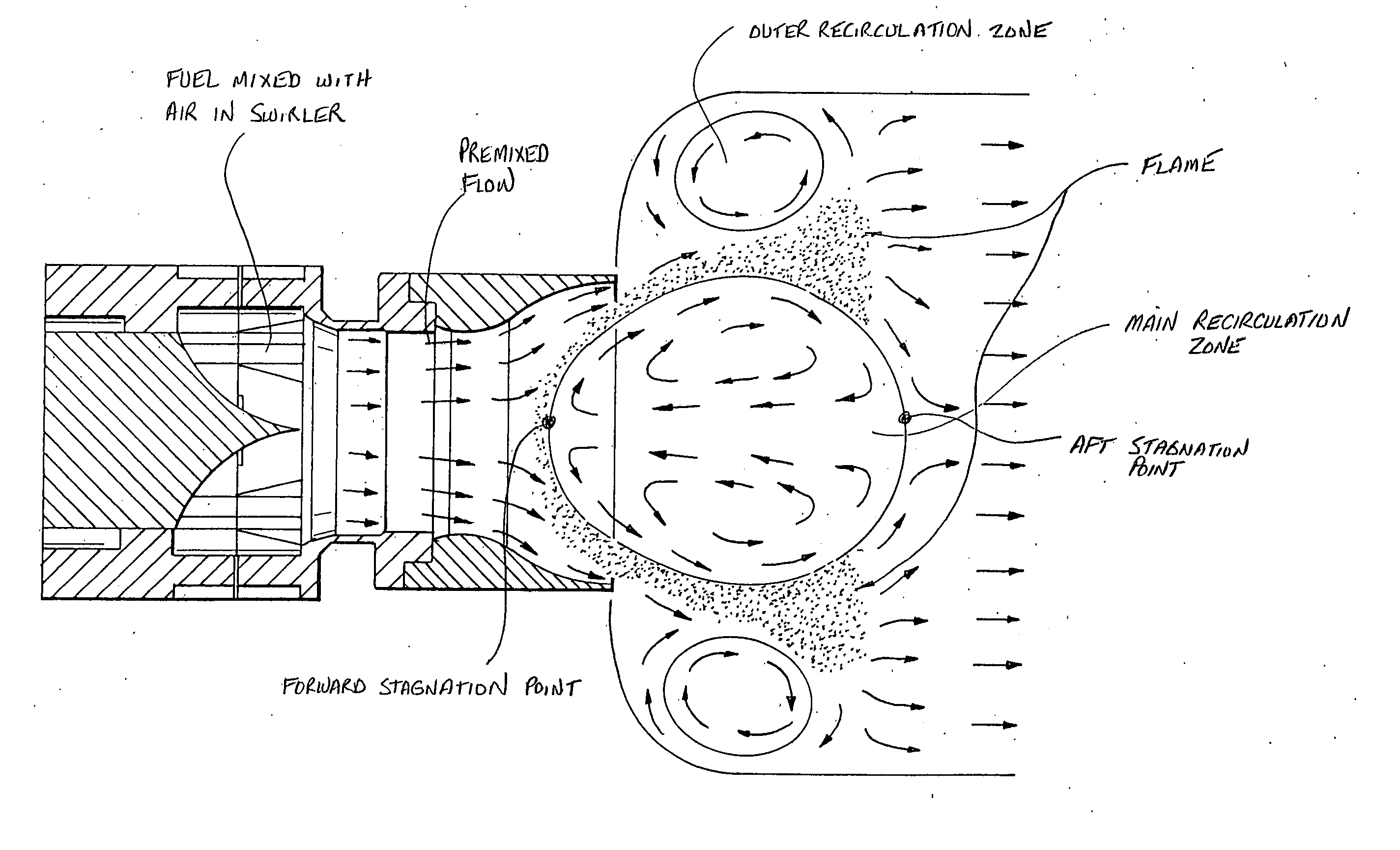
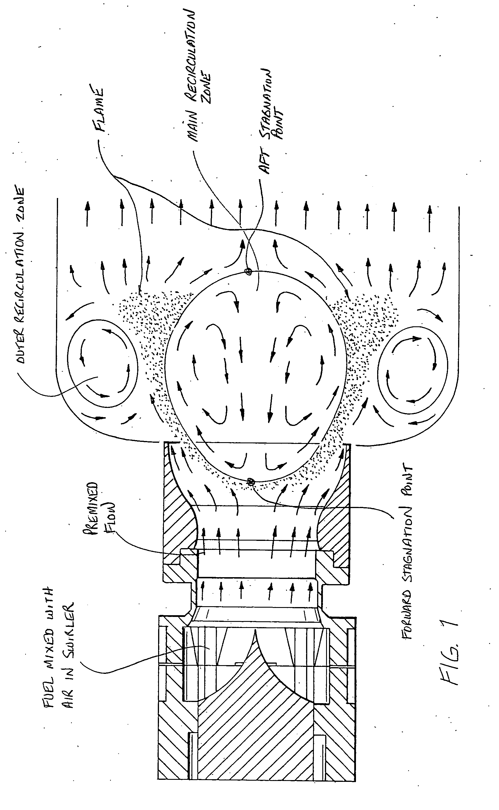
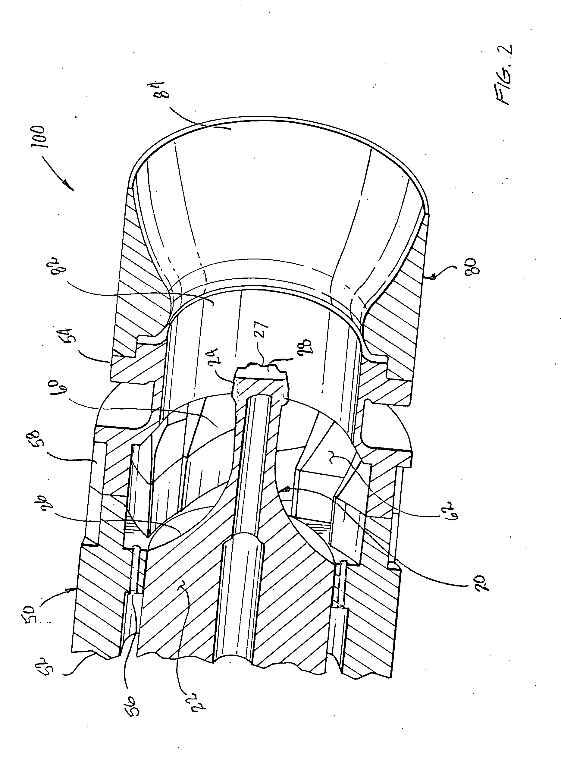
[0035] Referring now to the drawings wherein like reference numerals identify similar structural aspects of the subject invention, there is illustrated in FIG. 2 a burner for a gas turbine combustor designated generally as reference numeral 100. Burner 100 uses a central bluff body flame holder 20 and a quarl device 80 to stabilize the combustion process. The burner 100 includes, among other elements, a cylindrical main body 50, a flame holder 20 and a quarl device 80. The main body 50 and the flame holder 20 may be attached to one another in a conventional manner, or held together by an interference fit, or mechanically interlocked.

[0036] The burner main body 50 includes axially opposed upstream and downstream end portions, 52 and 54, respectively. A plurality of axially-oriented fuel inlet passages 56 and a plurality of radially-oriented air inlet passages 58 are formed in main body 50. Those skilled in the art would readily appreciate that the location, quantity and orientation ...


PUM


Abstract

Disclose is a burner for a gas turbine combustor that uses a central bluff body flame holder and a quarl to shape the recirculation zone in order to stabilize the combustion process. The burner includes, among other elements, a cylindrical main body and a flame holder. The flame holder is disposed within a fuel-air mixing chamber and includes a base portion and an elongated bluff body. The base portion engages with the main body of the burner in a supporting manner and the elongated bluff body extends in an axially downstream direction from the base portion through the internal mixing chamber so as to position a combustion ignition point downstream of the internal mixing chamber. In a representative embodiment, the burner further includes a quarl device disposed adjacent to the downstream end portion of the burner main body. The quarl device defines an interior recirculation chamber and a burner exit. The interior recirculation chamber is adapted for receiving precombustion gases from the mixing chamber and for recirculating a portion of the combustion product gases in an upstream direction so as to aid in stabilizing combustion.

Description

CROSS REFERENCE TO RELATED APPLICATIONS [0001] This application claims priority to U.S. Provisional Patent Application No. 60 / 500,517 filed Sep. 5, 2003, which is herein incorporated by reference in its entirety.BACKGROUND OF THE INVENTION [0002] 1. Field of the Invention [0003] The subject invention relates to burners for gas turbines, and more particularly, to burners adapted to stabilize engine combustion, and still further, to burners which use a quarl device in combination with and a central bluff body flame holder to stabilize the combustion process. [0004] 2. Background of the Related Art [0005] Gas turbines are employed in a variety of applications including electric power generation, military and commercial aviation, pipeline transmission and marine transportation. In a gas turbine engine, fuel and air are provided to a burner chamber where they are mixed and ignited by a flame, thereby initiating combustion. Several major technical problems are associated with the combusti...

Claims


Application Information

Patent Timeline
IPC IPC(8): F23D14/74F23M3/00F23R3/18F23R3/28
CPCF23D14/74F23R3/286F23R3/18F23D2209/20F23D14/72F23R3/28
Inventor CORNWELL, MICHAELMILOSAVLJEVIC, VLADIMIR DUSAN
Owner SIEMENS AG
Why Eureka
Try Eureka