Method and apparatus for filling vias

a technology of vias and filling methods, applied in the field of process and apparatus, can solve the problems of impracticality of filling blind vias with conductors, high aspect ratio blind via filling, and extremely difficult plating

Active Publication Date: 2005-05-19
GLOBALFOUNDRIES US INC
View PDF26 Cites 59 Cited by
  • Summary
  • Abstract
  • Description
  • Claims
  • Application Information

AI Technical Summary

Benefits of technology

[0027] The apparatus in accordance with the invention may further comprise a mechanism for moving the piston housing so that the seal is compressed for filing the vias. The mechanism for moving the piston housing may further move the piston housing to a position wherein the seal is compressed to a lesser degree than when the vias are filled, to thereby allow the piston housing to be moved so that the piston housing is disposed so as to be in a position to fill vias of one or more successive portions of the wafer with paste delivered to the opening.

Problems solved by technology

Of all the key technology elements described above, that which is most problematic is the filling of high aspect ratio blind vias with conductor.
Filling with common metals by PVD or CVD methods is impractical, while plating becomes extremely difficult due to the tendency for the plated side walls to “breadloaf” at the top, cutting off the via from further filling, and trapping plating solution in a central void.
Even if these or other methods of solid metal filling, such as filling with molten metal, could be made to work, typical metals have a large coefficient of thermal expansion (CTE) mismatch with silicon.
There are three potential problems associated with large CTE mismatches between the vias and the silicon substrate: delamination at the via side walls; cracking of the silicon substrate between vias; and piston-like rupture of any overlying or underlying structures or thin films in contact with the top / bottom surfaces of the vias.
Conventional screen printing lacked a process for removing the gas from the resin after the printed after curing, causing cracking or warping during the high temperature process.
The method is also not well suited to semiconductor processing where substrates are round rather than rectangular.
The linear motion of the squeegee blade 38 then leads to buildup at either end of the tool necessitating some method of regular cleaning, and a great waste of the conductive fill paste.
Since a mold is obviously a rigid plate containing etched regions of specific shapes, if these shapes take the form of cylinders then the problem is essentially one of filling blind vias.
Specifically, the method does not employ vacuum which is a practical necessity for complete filling of small, high aspect ratio blind vias.
Filling such small blind features with viscous paste without the aid of vacuum is highly problematic if not impossible.

Method used


Image

  • Method and apparatus for filling vias
  • Method and apparatus for filling vias
  • Method and apparatus for filling vias

Examples


Embodiment Construction

[0057] Variations described for the present invention can be realized in any combination desirable for each particular application. Thus particular limitations, and / or embodiment enhancements described herein, which may have particular advantages to the particular application need not be used for all applications. Also, it should be realized that not all limitations need be implemented in methods, systems and / or apparatus including one or more concepts of the present invention.

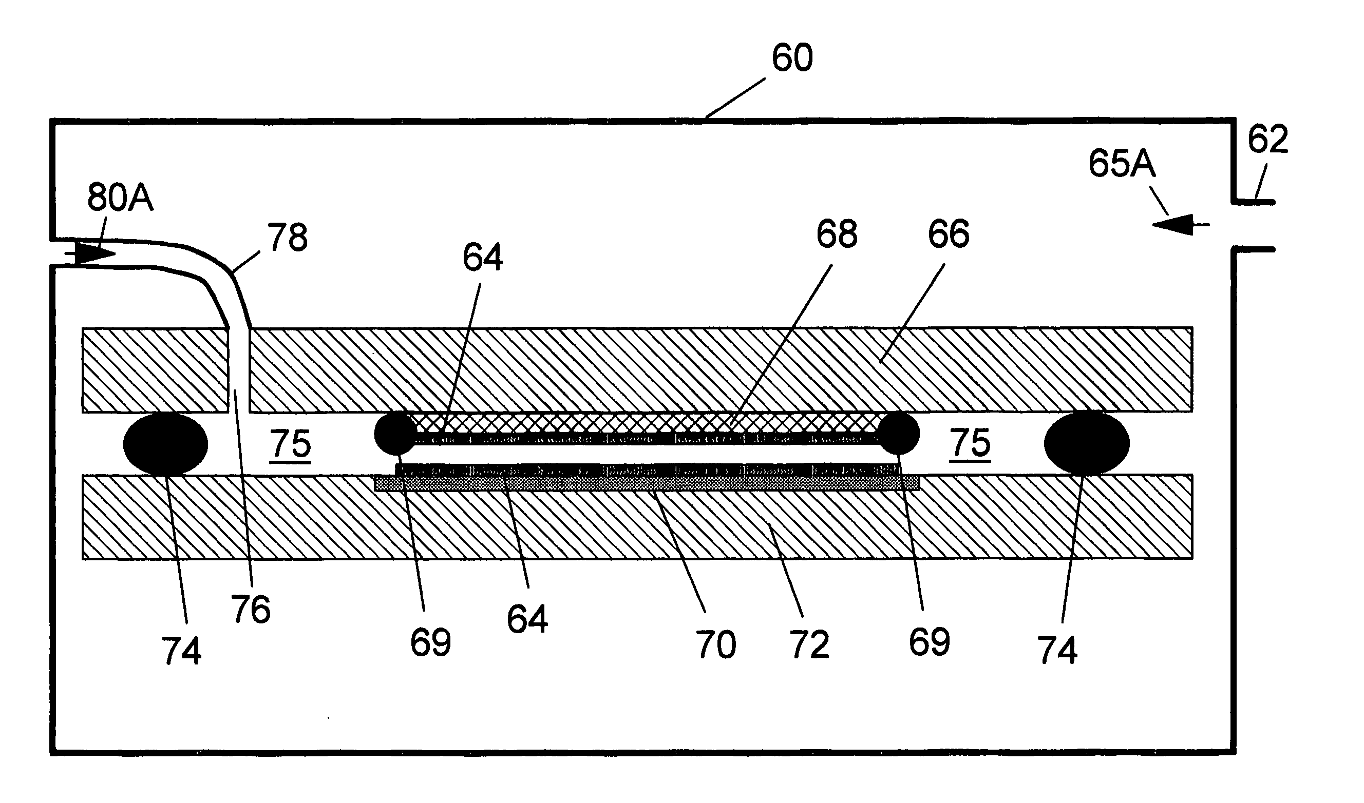
[0058] Referring to FIG. 4A, in a first apparatus and method in accordance with the invention, an outer processing chamber 60 has an outer vacuum port 62 to which a vacuum source (not shown) is connected. Chamber 60 is evacuated, as represented by arrow 65, through port 62. Conductive paste 64 is applied to a portion of one face of a top plate or piston 66, which is coated with Teflon or another nonstick and compliant surface material 68.

[0059] As used herein, the term paste refers to any material, and espec...


PUM


Abstract

A method for filling vias, and in particular initially blind vias, in a wafer, and various apparatus for performing the method, comprising evacuating air from the vias; trapping at least a portion of the wafer and a paste for filling the vias between two surfaces; and pressurizing the paste to fill the vias.

Description

FIELD OF THE INVENTION [0001] This invention is directed to a process and apparatus, and in particular tooling, for enabling the creation of filled, and preferably conductive, vias and through-vias in a semiconductor substrate. More particularly, it is directed to a process and apparatus for enabling the filling of such vias. BACKGROUND OF THE INVENTION [0002] There are many advantages to using silicon as a substrate for electronic packaging, rather than traditional ceramic and organic laminate packaging. Some of the key features of the silicon carrier include: the ability to create high performance wiring and joining at much finer pitch than typical packaging, the ability to join heterogeneous technologies or different generation technologies for high speed applications, the ability to integrate passives, MEMS or optical fibers, the ability to add silicon functionality to the carrier package in addition to wiring, the ability to dramatically increase the I / O density, and for many a...

Claims


Application Information

Patent Timeline
Patent Type & Authority Applications(United States)
IPC IPC(8): H01L23/12H01L21/48H01L21/60H01L21/76H01L23/14H01L25/04H01L25/18H05K3/34
CPCH01L21/486H01L23/147H01L2924/15311H01L2224/16225H01L2924/10253H01L2924/1461H01L2924/00
Inventor ANDRY, PAUL S.CASEY, JON A.HORTON, RAYMOND R.PATEL, CHIRAQ S.SPROGIS, EDMUND J.SUNDLOF, BRIAN R.
Owner GLOBALFOUNDRIES US INC
Why Eureka
Try Eureka