Belt-type continuously variable transmission

a transmission and continuously variable technology, applied in the direction of gearing, gearing elements, hoisting equipment, etc., can solve the problems of wasting engine power, unable to meet the performance of the above-mentioned transmission, and being subjected to a high load, so as to reduce the load and speed up the speed.

Inactive Publication Date: 2005-05-19
JATCO LTD
View PDF15 Cites 28 Cited by
  • Summary
  • Abstract
  • Description
  • Claims
  • Application Information

AI Technical Summary

Benefits of technology

[0007] Accordingly, an object of the present invention is to provide a belt-type continuously variable transmission which is free of the above-mentioned drawbacks.
[0008] In accordance with the present invention, there is provided a belt-type continuously variable transmission which can reduce a load applied to the oil pump and can carry out a quick speed change.

Problems solved by technology

However, due to the inherent construction of the hydraulic system, the transmission of the above-mentioned transmission fails to exhibit a satisfied performance.
That is, because of need of high line pressure, an associated oil pump is subjected to a high load, which tends to waste the engine power.
Furthermore, since the pressure receiving area of the piston chamber is larger than that of a speed change piston chamber, a differential thrust (viz., a difference between a thrust with which the metal belt is pressed against the drive pulley and a thrust with which the metal belt is pressed against the driven pulley) needed by the transmission at a speed change fails to have a satisfied value and thus the speed change is not quickly or smoothly carried out.

Method used


Image

  • Belt-type continuously variable transmission
  • Belt-type continuously variable transmission
  • Belt-type continuously variable transmission

Examples


Embodiment Construction

[0019] In the following, the present invention will be described in detail with reference to the accompanying drawings.

[0020] For ease of understanding, various directional terms, such as, right, left, upper, lower, rightward and the like are used in the following description. However, such terms are to be understood with respect to a drawing or drawings on which the corresponding part or portion is shown.

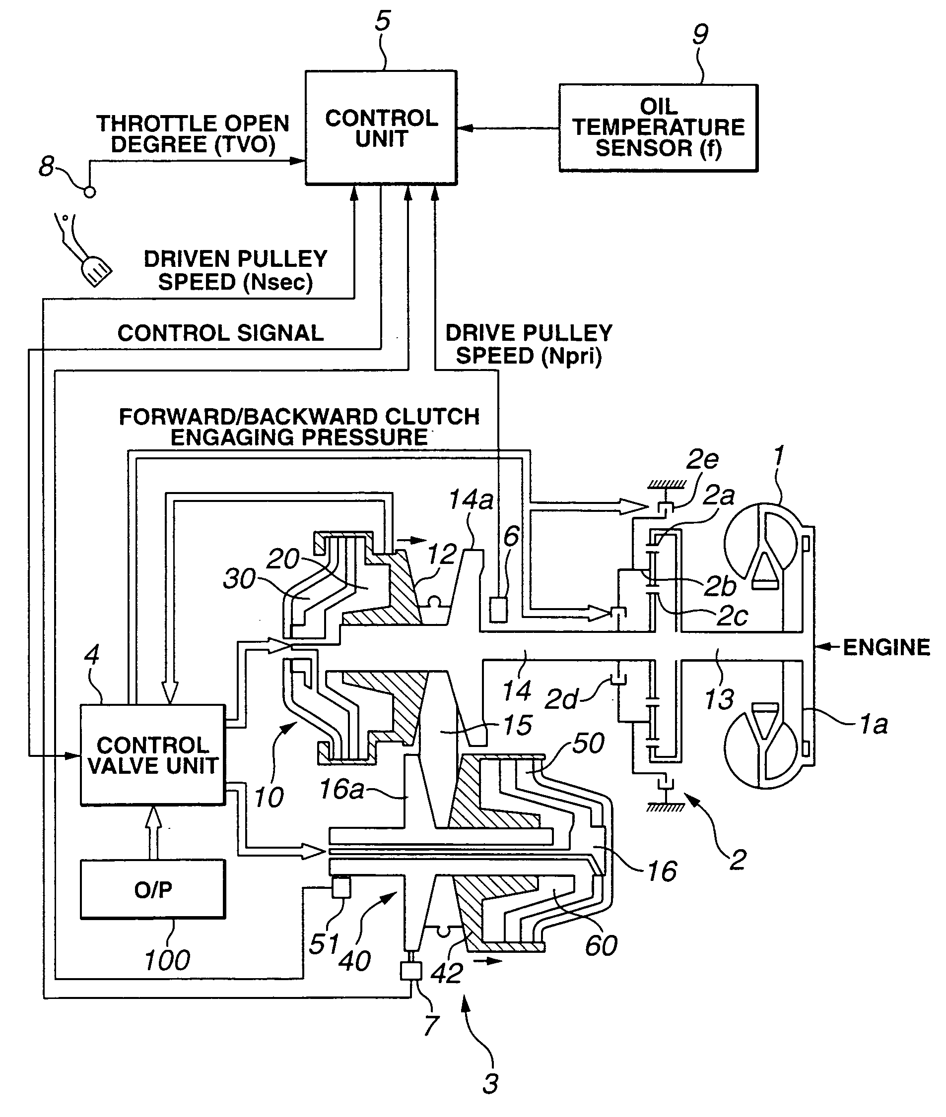
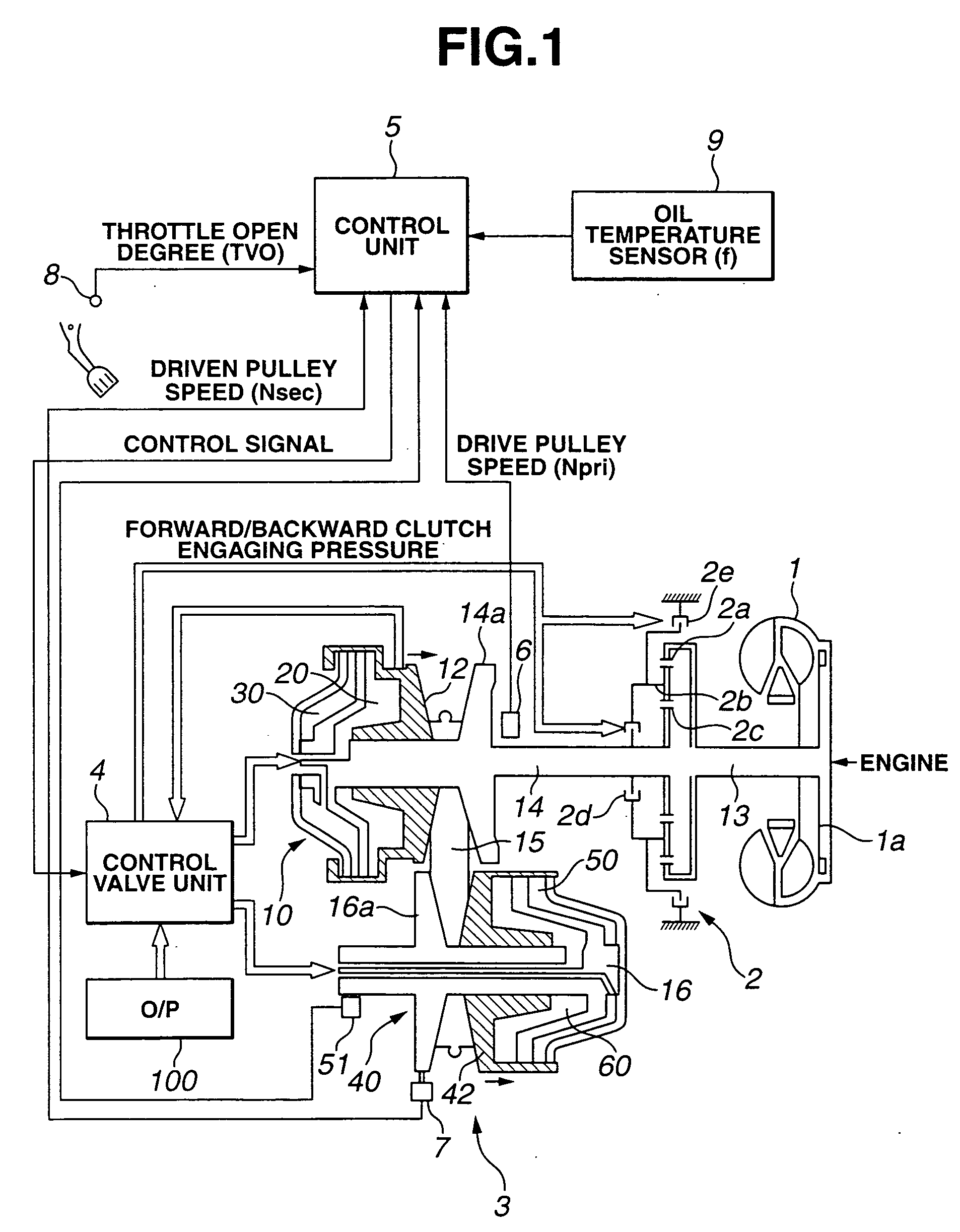
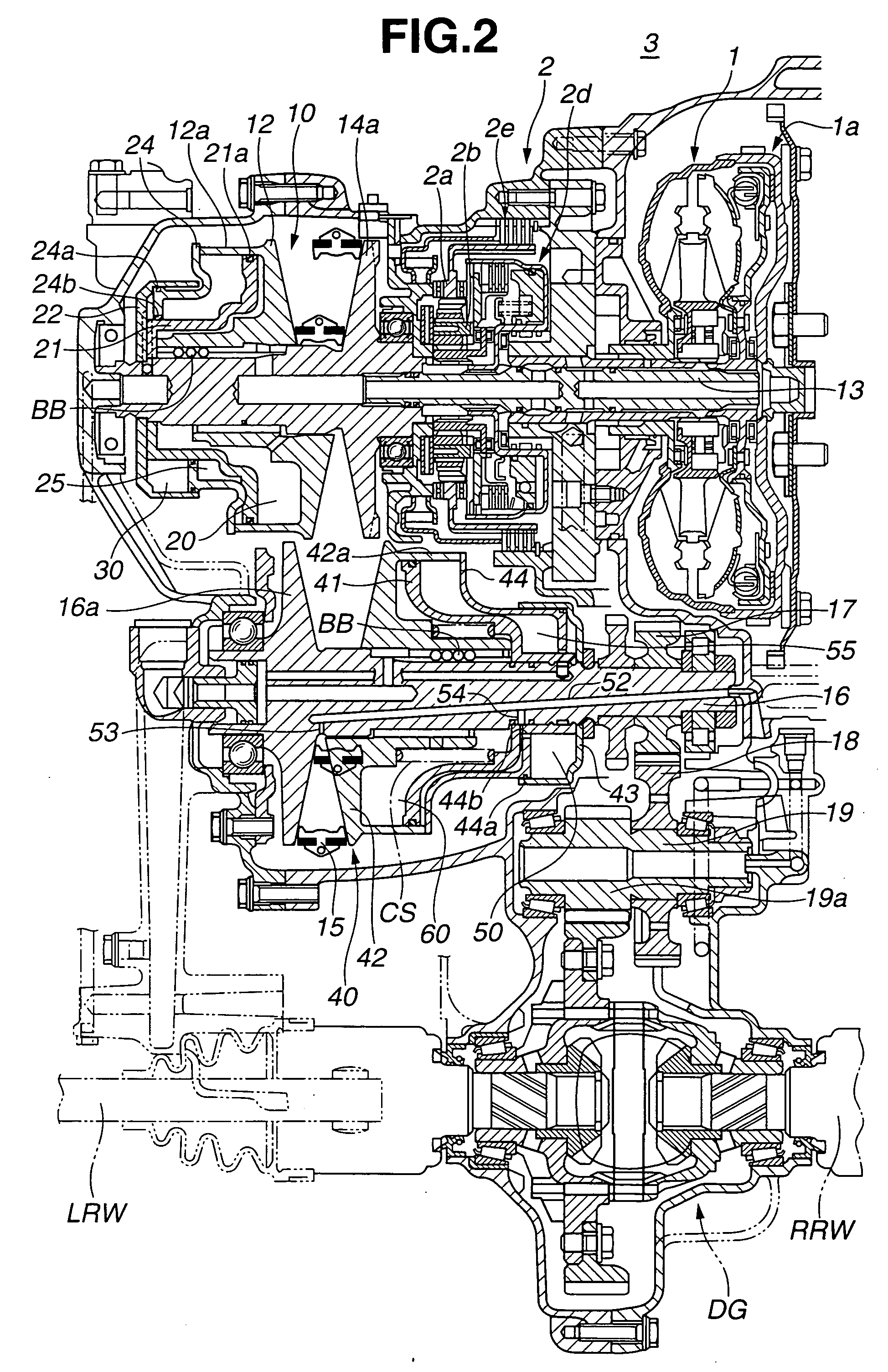
[0021] Referring to FIGS. 1 and 2, there is shown a belt-type continuously variable transmission 3 of the present invention incorporated. FIG. 1 is a drawing showing a hydraulic control system of the transmission and FIG. 2 is a sectional view of the transmission. However, FIG. 2 shows two conditions assumed by drive and driven pulleys 10 and 40 which will be described in detail hereinafter.

[0022] As is understood from these drawings, the transmission 3 has a torque converter 1 connected thereto. Although not shown in the drawing, an output shaft of an engine (viz., internal com...


PUM


Abstract

A belt-type continuously variable transmission comprises a drive pulley including cylinder and cramp chambers which vary an effective radius of the drive pulley when applied with a hydraulic pressure, a driven pulley including cylinder and cramp chambers which vary an effective radius of the driven pulley when applied with a hydraulic pressure, a belt operatively put around the drive and driven pulleys and a hydraulic circuit that applies the cylinder and cramp chambers of the drive and driven pulleys with the hydraulic pressure to vary the effective radii of the drive and driven pulleys. The hydraulic circuit includes a line pressure passage that has a line pressure regulating valve installed therein for producing a line pressure in the line pressure passage. The cramp chambers of the drive and driven pulleys are substantially the same in a pressure receiving area and are connected to the line pressure passage to be fed with the line pressure.

Description

BACKGROUND OF THE INVENTION [0001] 1. Field of the Invention [0002] The present invention relates in general to belt-type continuously variable transmissions in which a metal belt is put around a drive pulley (or primary pulley) and a driven pulley (or secondary pulley), each pulley having a width-variable V-groove therearound for operatively receiving therein the metal belt. More specifically, the present invention is concerned with improvement in a hydraulic system that controls the groove width of the drive and driven pulleys. [0003] 2. Description of the Related Art [0004] In order to clarify the task of the present invention, the belt-type continuously variable transmission disclosed in Japanese Laid-open Patent Application (Tokkai) 2000-27959 will be briefly explained before describing the detail of the present invention. [0005] In this transmission of the related art, a hydraulic system is employed in which a torque cam mechanism is arranged in a torque input side, so that a ...

Claims


Application Information

Patent Timeline
Patent Type & Authority Applications(United States)
IPC IPC(8): F16H9/00F16H55/56F16H9/18F16H61/00F16H61/662F16H63/06
CPCF16H55/56F16H61/0021F16H63/065F16H61/66263F16H61/66259
Inventor KATOU, YOSHIAKI
Owner JATCO LTD
Why Eureka
Try Eureka