Balloon catheter with kink resistant distal segment

Inactive Publication Date: 2005-05-19
INNOVATIONAL HLDG LLC
View PDF2 Cites 20 Cited by
  • Summary
  • Abstract
  • Description
  • Claims
  • Application Information

AI Technical Summary

Benefits of technology

[0003] The present invention relates to rapid exchange balloon catheter having a kink resistant distal segment just proxi

Problems solved by technology

In these balloon catheter systems a flexible portion of the catheter proximal of the balloon is an important region which is prone to kinking.
Howeve

Method used


Image

  • Balloon catheter with kink resistant distal segment
  • Balloon catheter with kink resistant distal segment
  • Balloon catheter with kink resistant distal segment

Examples


Embodiment Construction

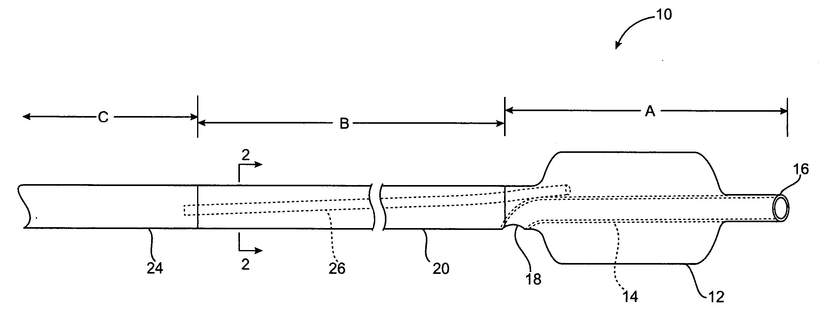
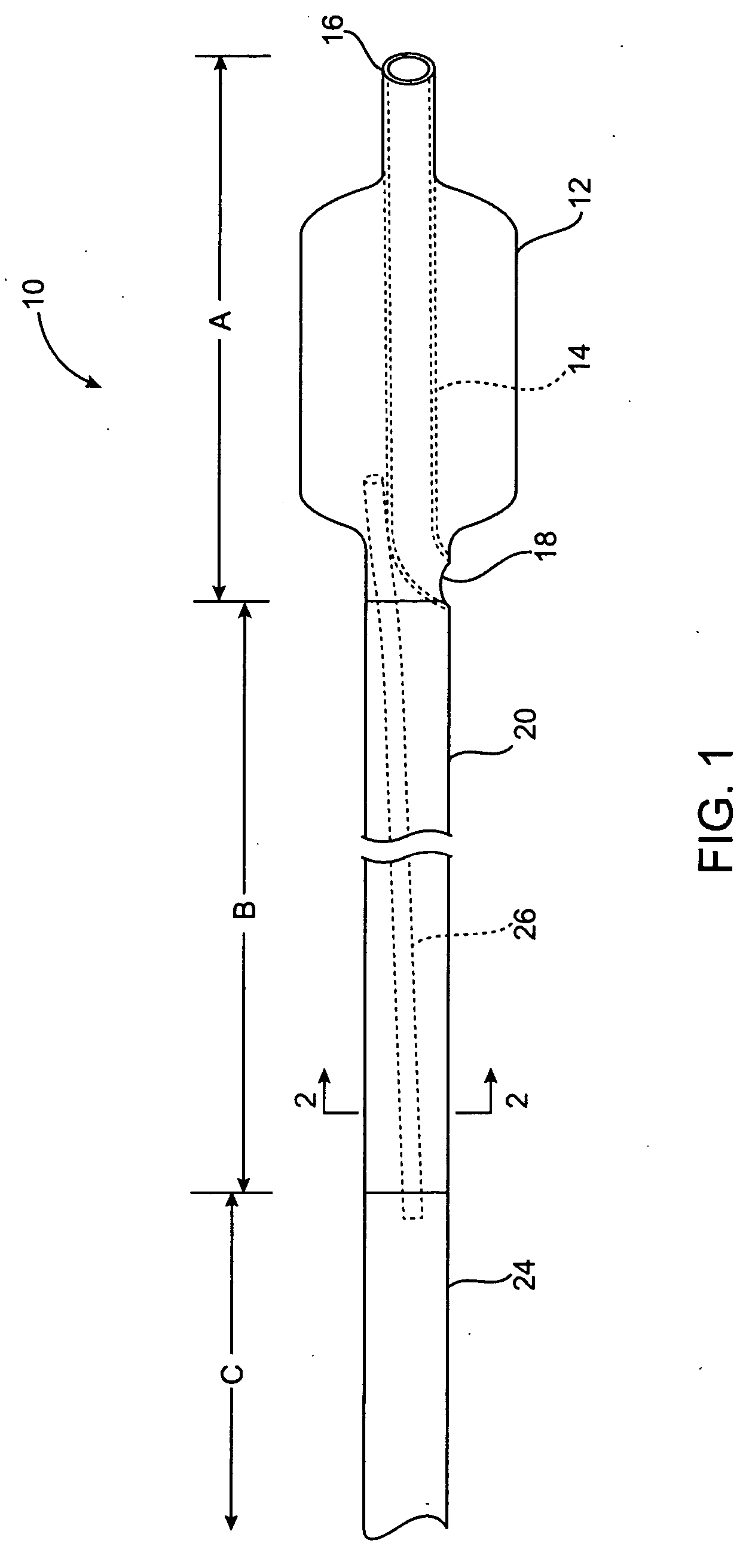
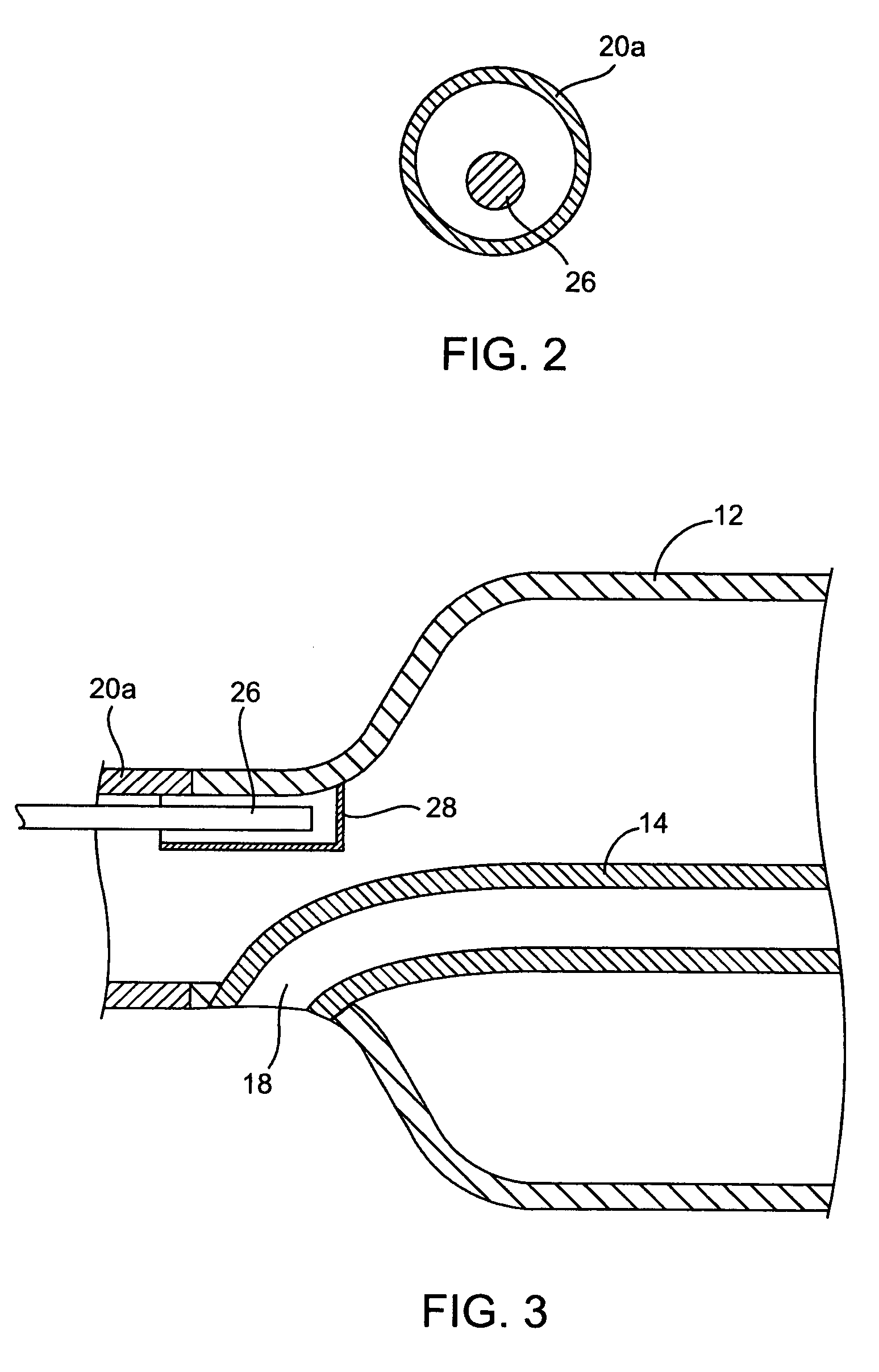
[0016] The dilation catheter 10 of FIG. 1 includes a balloon segment A, a distal segment B, and a proximal segment C. The balloon segment A includes a balloon 12 which is shown in an expanded condition in FIG. 1. Within the balloon 12 is a guidewire tube 14 extending from a distal port 16 to a proximal port 18. The guidewire tube 14 extends a very short distance proximally of the balloon with the proximal port 18 of the guidewire tube 14 being adjacent to or close to the balloon to improve the speed and ease of catheter exchanges.

[0017] The dilation catheter 10 shown herein is designed as an angioplasty catheter or for delivery of a coronary stent. The stent can be a fully balloon expandable stent or a partially balloon expandable stent. The stent can also be permanent or biodegradable. In addition to use for angioplasty or stent deployment, the balloon catheter can also be used for other known purposes.

[0018] The balloon 12 may be formed by any known method, such as by elongating...


PUM


Abstract

A rapid exchange balloon catheter has a kink resistant distal catheter segment just proximal of the balloon with a kink resisting member to provide pushability and kink resistance while maintaining flexibility. The kink resistant distal segment allows the rapid exchange guidewire tube to be shortened for a more rapid guidewire exchange.

Description

BACKGROUND [0001] Rapid exchange balloon catheters are described in U.S. Pat. Nos. 4,762,129 and 5,040,548 which are incorporated herein by reference. These rapid exchange catheters include a distal guidewire lumen which extends through the balloon from a distal end of the balloon to a guidewire exit port proximal of the balloon. In these balloon catheter systems a flexible portion of the catheter proximal of the balloon is an important region which is prone to kinking. This portion of the catheter proximal of the balloon and distal to a stiffer proximal catheter section should be simultaneously very flexible to navigate the coronary arteries, have good column strength to provide pushability, and have good kink resistance. [0002] Rapid exchange catheters have the advantage that the guidewire passes only through a short segment at the distal end of the catheter. This greatly decreases the time required to exchange catheters compared to an over the wire catheter in which the guidewire...

Claims


Application Information

Patent Timeline
IPC IPC(8): A61F2/958A61M29/00
CPCA61M25/10A61M2025/1093A61M2025/0183A61M2025/0063
Inventor SHANLEY, JOHN F.FISHER, BEAU M.
Owner INNOVATIONAL HLDG LLC
Why Eureka
Try Eureka