
Method and filter arrangement for digital recursive filtering in the time domain

Inactive Publication Date: 2005-05-19
INFINEON TECH AG
View PDF6 Cites 2 Cited by
  • Summary
  • Abstract
  • Description
  • Claims
  • Application Information

AI Technical Summary

Benefits of technology

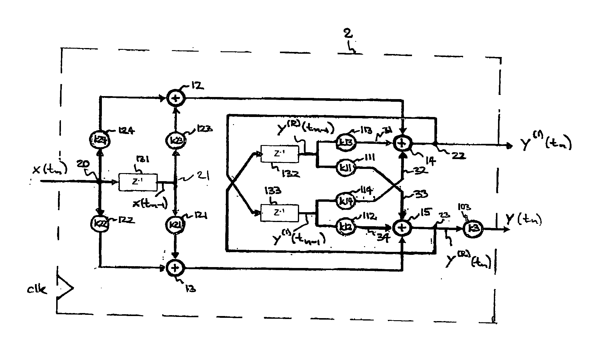
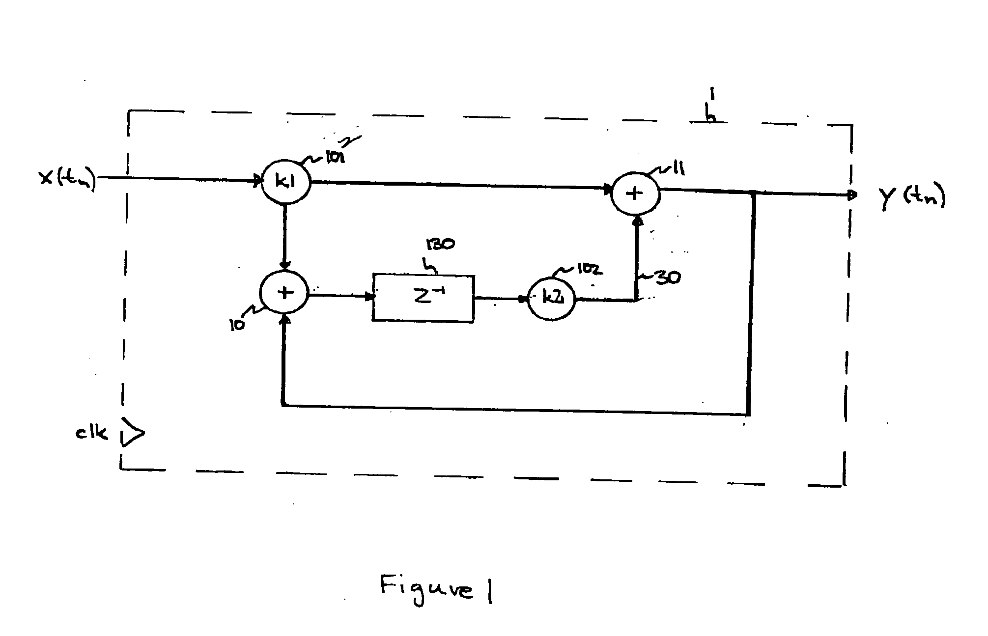
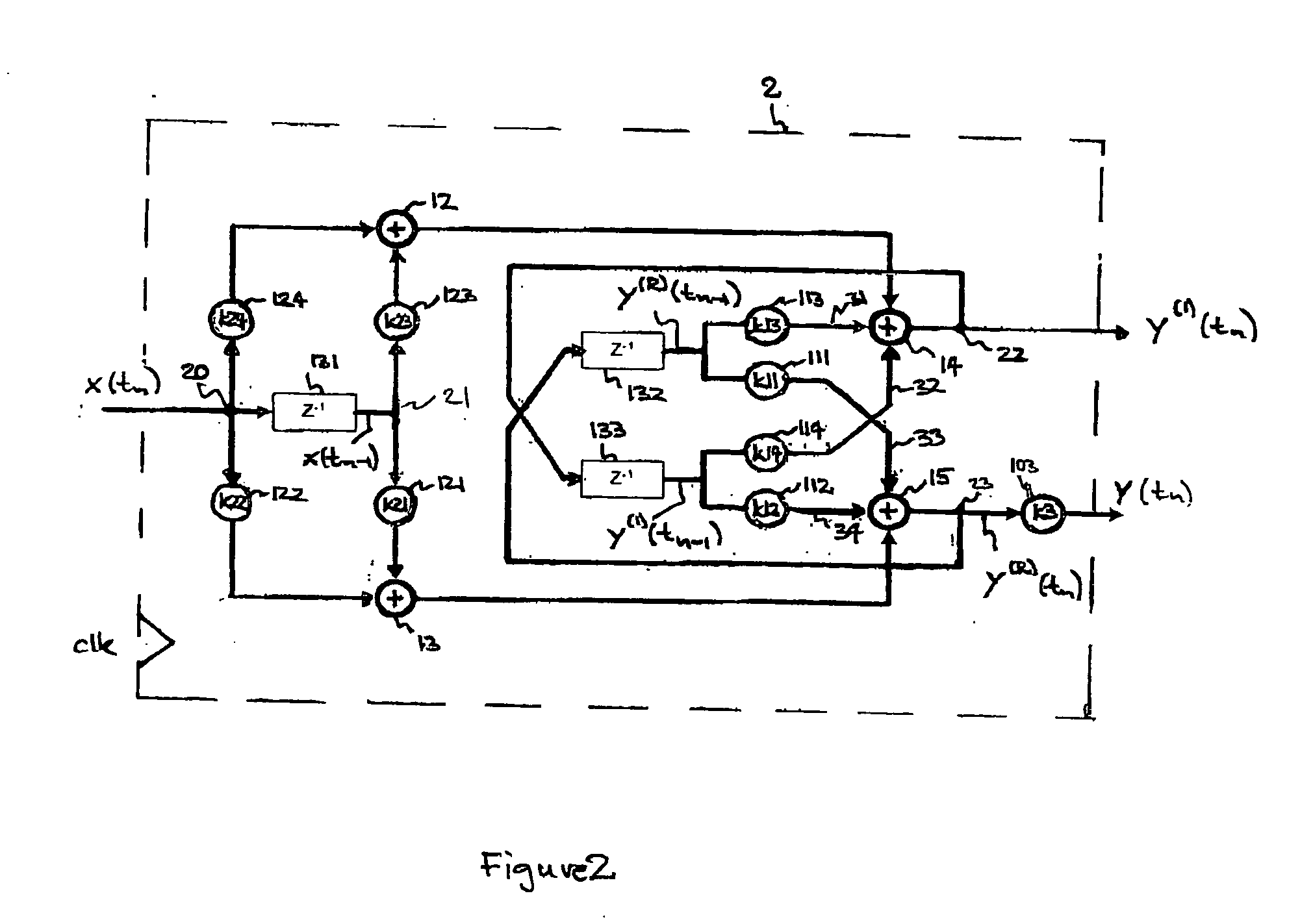
[0019] It is an advantage of the inventive method and filter arrangement that the number of complex multiplications, that need to be performed for providing the filter output at a certain time tn, is only proportional to N2. Therefore, the inventive method and filter arrangement reduces the calculational effort to the order of O(N). This is because of the recursive architecture, the current filter output signal corresponding to the time tn, depends on the filter output signal of the preceding clock cycle corresponding to tn-1.
[0020] Since the basic elements of the filter arrangement are only first and second order recursive filter stages, the required area on a chip and the power consumption is low with respect to prior art filters. Further, any filtering of an input signal according to any desired rational filter transfer function is realized by the inventive method and filter arrangement. Since the inventive method and filter arrangement only resorts to first an second order stages the invention is robust against instabilities that usually arise in higher order filtering.
[0021] Therefore, the inventive method and filter arrangement is faster than prior art digital filters, easy to implement on a chip, requires a smaller area on a chip and shows a low power consumption.
[0024] In another preferred embodiment of the inventive digital recursive filter arrangement, the computation unit is replaced by a memory device coupled to the interface for providing the filter coefficients for the first and second filter stages. This has the advantage that if the recursive filter arrangement is used with a fixed filter transfer function, the corresponding filter coefficients can be calculated externally and stored in the memory device. Then the entire filter arrangement becomes less complex and easier to integrate on a chip. The memory device may be a random access memory coupled to a computer, a read-only memory, an erasable read-only memory or any appropriate implementation for storing filter coefficients.
[0025] In yet another preferred embodiment of the recursive filter arrangement, there is only one delay element in a signal path between the input and the output of the inventive filter arrangement. This has the advantage that the delay time through the inventive filter arrangement is two clock cycles.
[0039] This alternative embodiment of the invention is particularly advantageous for realizing a digital filter for filtering with a fixed transfer function, because the first and second filter stages are implemented accordingly. This alternative embodiment of the invention does not require an interface or computation unit and is easy to implement on a chip.

Problems solved by technology

Calculating such a convolution integral in the time domain is very elaborate and time-consuming, because the integral has to be approximated by a discrete sum over a number N of samples of the integrand multiplied by the sampling interval.

Method used


Image

  • Method and filter arrangement for digital recursive filtering in the time domain
  • Method and filter arrangement for digital recursive filtering in the time domain
  • Method and filter arrangement for digital recursive filtering in the time domain

Examples


Embodiment Construction

[0007] This object is met by a method for digital recursive filtering of an input signal according to a rational filter transfer function discussed below and a digital recursive filter arrangement, also discussed below, as well as other embodiments of the invention.

[0008] One embodiment of the invention is a method for digital recursive filtering an input signal according to a rational filter transfer function clocked by a clock signal comprising the following steps: [0009] (a) providing first and second order rational functions corresponding to the rational filter transfer function; [0010] wherein the following steps are performed iteratively: [0011] (b1) determining a plurality of intermediate signals from the input signal using the first and second order rational transfer functions and one or more previous intermediate signals determined in a preceding clock cycle of the clock signal; [0012] (b2) adding the plurality of intermediate signals to generate at least one filter output...


PUM


Abstract

A method and apparatus for fast digital filtering that requires only filter stages of first and second order. A desired rational filter transfer function is represented as a sum of first and second order intermediate transfer functions. A time dependent input signal is first fed in parallel into a plurality of first and second order intermediate recursive filter stages. Then, the outputs of the intermediate filter stages are summed up to an output filter signal that corresponds to the desired rational filter transfer function. The method and apparatus reduces the amount of calculational effort to the order of O(N), where N denotes the number of sampling points in the time domain, because the digital filtering is based on a discrete recursive convolution in the time domain.

Description

FIELD OF THE INVENTION [0001] The invention relates to a method for digital recursive filtering according to a rational filter transfer function, a filter arrangement for filtering accordingly and corresponding digital filter stages. BACKGROUND OF THE INVENTION [0002] In digital signal processing, electrical signals are represented by a sequence of binary signals that are to be processed. A major part of this digital processing is done by digital filtering. A binary or digital input signal is put through a digital filter structure that alters the input signal according to its particular filter transfer function and is output as a desired output signal. For instance, a low-pass filter reduces the bandwidth of an input signal. [0003] In most of the cases, the signals in digital signal processing represent time-dependent processes. An input signal x(t) is converted into an output signal y(t) by a filter system which is characterized by its pulse response h(t) or its transfer function, ...

Claims


Application Information

Patent Timeline
IPC IPC(8): H03H17/04
CPCH03H17/04H03H17/0223
Inventor MATTES, HEINZGREGORIUS, PETERLINDT, PAUL GEORG
Owner INFINEON TECH AG
Learn More