Electrolytic water generation apparatus having stable performance of electrolytic water generation

Inactive Publication Date: 2005-05-26
SANYO ELECTRIC CO LTD
View PDF5 Cites 23 Cited by
  • Summary
  • Abstract
  • Description
  • Claims
  • Application Information

AI Technical Summary

Benefits of technology

[0009] In view of the foregoing, an object of the present invention is to provide an electro

Problems solved by technology

When water including mineral components such as tap water is used as the dilution water, the aforementioned electrolytic water generation apparatus had the problem that the scale and the like of the mineral component will adhere to the negative side of the electrodes.
There was a problem that the electrodes are consumed in a short p

Method used


Image

  • Electrolytic water generation apparatus having stable performance of electrolytic water generation
  • Electrolytic water generation apparatus having stable performance of electrolytic water generation
  • Electrolytic water generation apparatus having stable performance of electrolytic water generation

Examples


first embodiment

[0031] Embodiments of the present invention will be described hereinafter with reference to the drawings.

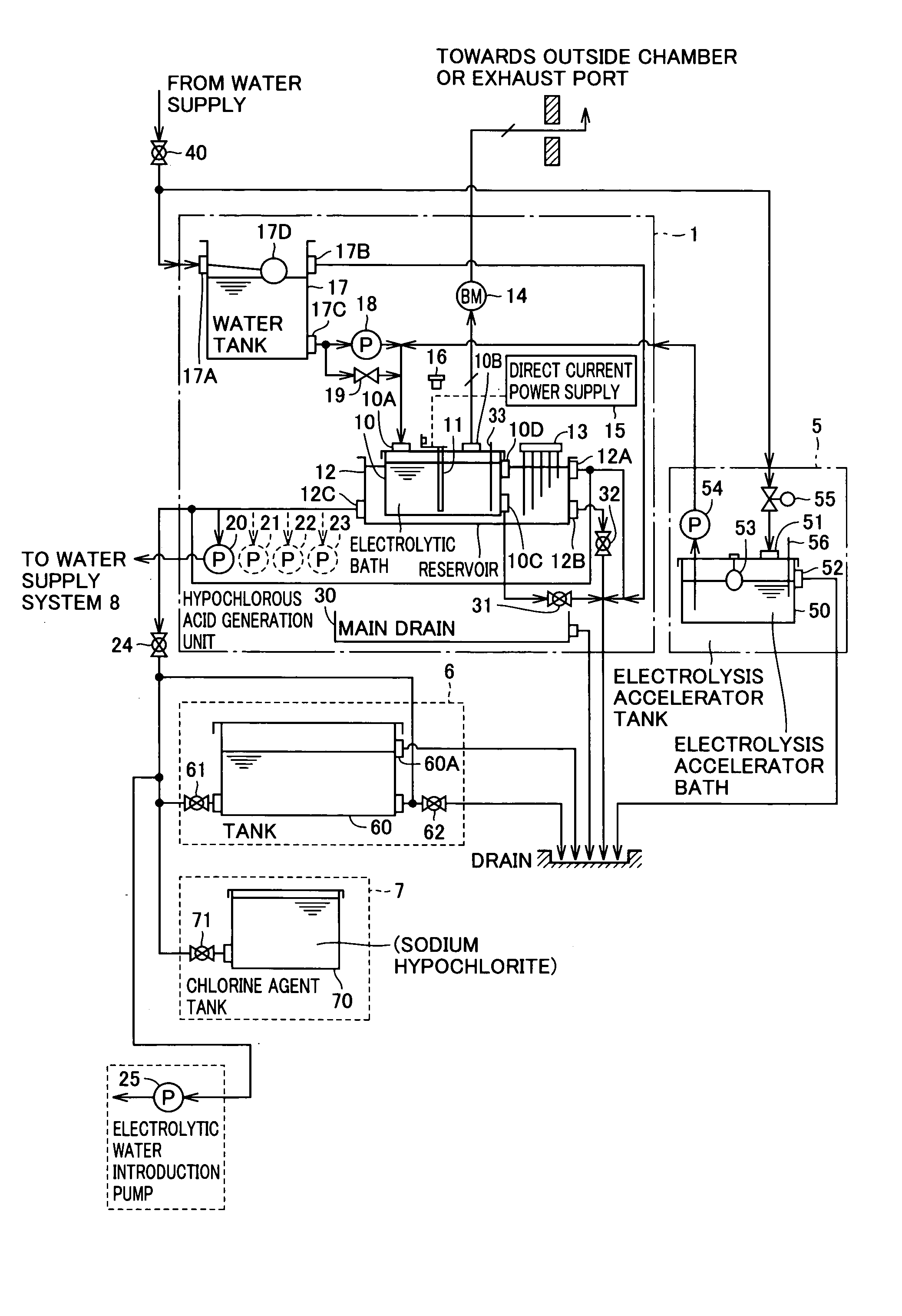
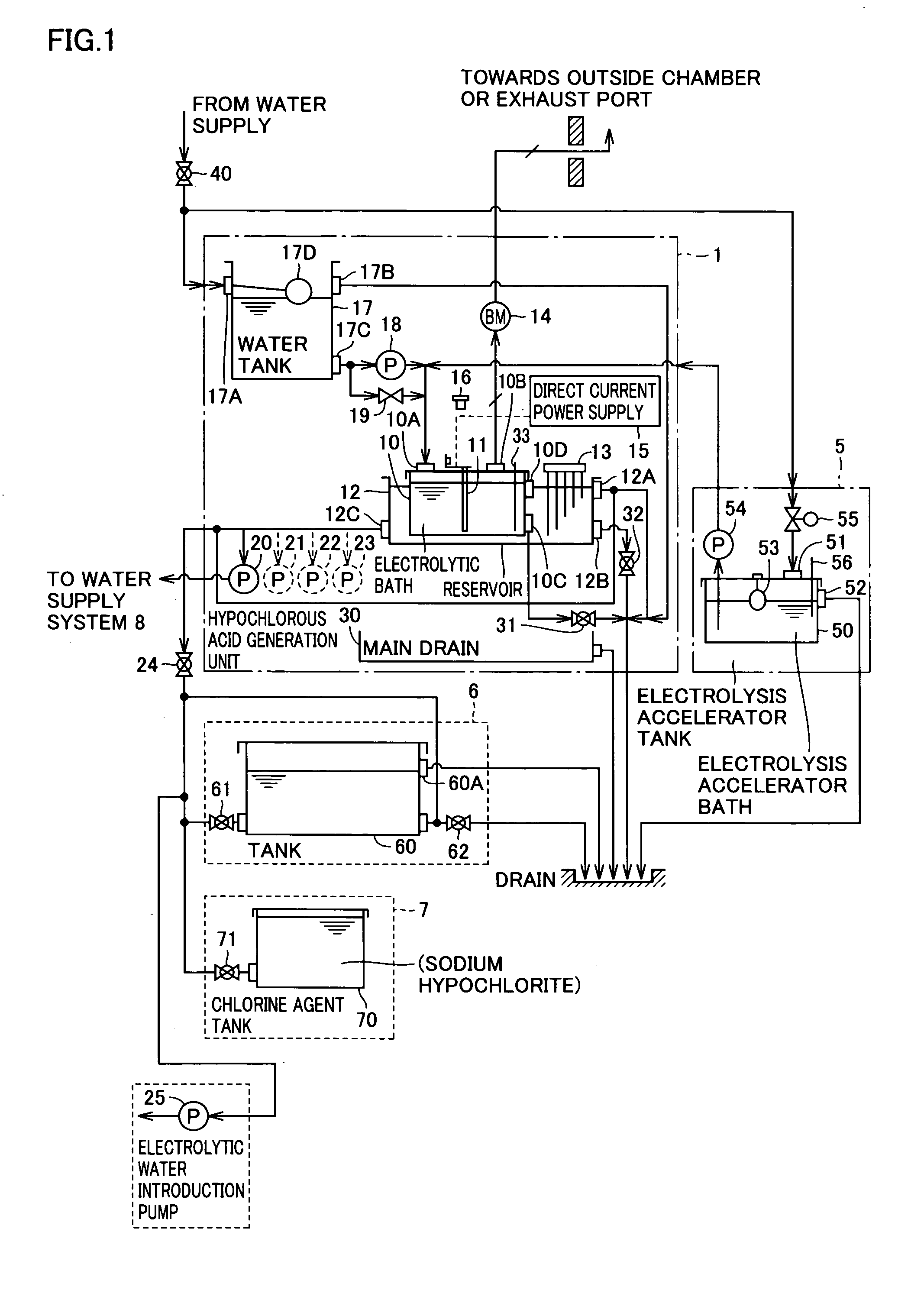
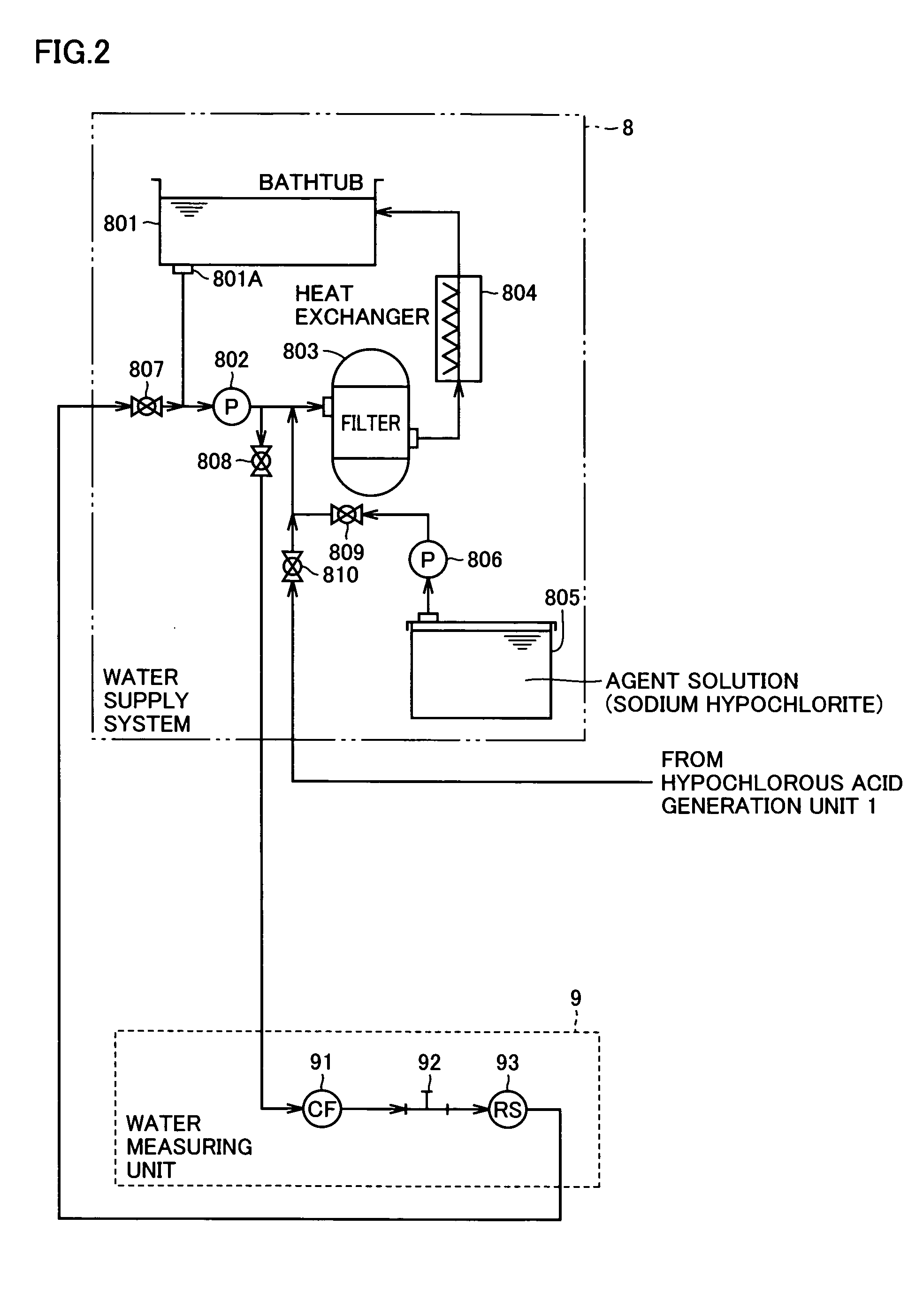
[0032] A functional configuration of a water processing system will be described with reference to FIGS. 1 and 2 in which arrows indicate the piping and flow through which liquid or gas pass through.

[0033] In the water processing system, water from tap water or the like is supplied as the water to be treated to the electrolytic water generation apparatus. The electrolytic water generation apparatus applies electrolysis on the water to be treated to generate hypochlorous acid in the water to be treated. The electrolytic water generation apparatus supplies the under-treating water now including hypochlorous acid by electrolysis to another apparatus such as a water supply system and the like.

[0034] The electrolytic water generation apparatus is mainly constituted of a hypochlorous acid generation unit 1 and an electrolysis accelerator tank 5. Water to be treated is introduced fro...

second embodiment

[0074] In the previous first embodiment, control is provided such that the current value of the electrodes of the first stage in electrolytic bath 10 is within a predetermined range (the range of F2) by adjusting the electrolysis accelerator added into electrolytic bath 10 to control the concentration of the electrolysis accelerator in electrolytic bath 10 in the electrolytic water generation apparatus of FIG. 1, as described with reference to FIGS. 5 and 6 in particular.

[0075] In the second embodiment, the introducing amount of the electrolysis accelerator is adjusted when pump 54 identified as the pump for introducing the electrolysis accelerator is ON in accordance with the temperature of the electrolysis accelerator (saturated sodium chloride solution) in electrolysis accelerator bath 50 so that the concentration of the electrolysis accelerator is adjusted further properly in an electrolytic water generation apparatus having a configuration similar to that of the first embodime...


PUM

PropertyMeasurementUnit
Temperatureaaaaaaaaaa
Concentrationaaaaaaaaaa
Currentaaaaaaaaaa

Abstract

Into an electrolytic bath storing water to be treated, saturated sodium chloride solution identified as an electrolysis accelerator is added from an electrolysis accelerator bath. The water to be treated is subjected to electrolysis. In the electrolytic bath, water to be treated is introduced from an inlet during the electrolysis process. The water subjected to electrolysis in electrolytic bath is output to a reservoir via an overflow port. A plurality of electrode pairs are provided in the electrolytic bath. During the electrolysis process, the value of the current flowing across the electrodes of the electrode pair arranged most upstream of a water channel from the inlet to the overflow port in the electrolytic bath is detected, and control is provided such that the current value is within a predetermined range by adjusting the concentration of the accelerator in the electrolytic bath.

Description

BACKGROUND OF THE INVENTION [0001] 1. Field of the Invention [0002] The present invention relates to electrolytic water generation apparatuses, particularly an electrolytic water generation apparatus having a pair of electrodes immersed in water to be treated for converting the water to be treated into electrolytic water including a desired component by the electrolytic reaction of the electrode pair. [0003] 2. Description of the Related Art [0004] The technique of a conventional electrolytic water generation apparatus that generates sodium hypochlorite used for sterilization in the water supply through electrolytic reaction is disclosed. [0005] For example, Japanese Patent Laying-Open No. 07-216572 discloses the technique of an electrolytic water generation apparatus that dilutes saline with dilution water, and supplies the diluted saline to an electrolytic bath, whereby sodium hypochlorite is generated. [0006] When water including mineral components such as tap water is used as th...

Claims


Application Information

Patent Timeline
IPC IPC(8): C02F1/46C02F1/00C02F1/461C02F1/467C25B15/02C25D17/00
CPCC02F1/001C02F1/46109C02F1/4618C02F1/4674C02F2201/46125C02F2209/42C02F2201/4618C02F2209/006C02F2209/02C02F2209/30C02F2201/4617
Inventor INAMOTO, YOSHIHIROKAWAMURA, YOZOKISHI, MINORU
Owner SANYO ELECTRIC CO LTD
Why Eureka
Try Eureka