
Water contaminant indicators

a technology of water contaminant and indicators, applied in the direction of filtration separation, instruments, separation processes, etc., can solve the problems of unwanted and potentially harmful contamination of water, inactive chemical treatment medium, no direct indication of its useful life,

Inactive Publication Date: 2005-05-26
THE CLOROX CO
View PDF32 Cites 53 Cited by
  • Summary
  • Abstract
  • Description
  • Claims
  • Application Information

AI Technical Summary

Benefits of technology

The patent describes a gravity-flow liquid treatment system that includes a filter device that can visually indicate exposure to contaminants. The system has a low liquid head pressure, and the filter device has a first filter component that can change color to indicate exposure to particles, inorganic, and organic contamination. The system also includes at least one agent that can undergo a color-change reaction in response to contaminants. The technical effect of this patent is to provide a simple and effective way to visually indicate exposure to contaminants in liquid treatment systems, regardless of the method of liquid flow.

Problems solved by technology

Unwanted and potentially harmful contamination in water, especially drinking water, is of concern to many people.
A major drawback associated with chemical treatment is that the chemical treatment medium eventually becomes inactive, yet provides no direct indication that its useful life is over.
Although chemical treatment provides additional water purification not possible with mechanical filtration alone, it is difficult for consumers to have an indication that these systems are working actively except, of course, by the subjective taste of the treated water.
Many consumers are not aware of the specific chemical contaminants in their tap water.
Although current water treatment devices may be successful in removing these contaminants, a consumer has no direct indication of what has been removed.

Method used


Image

  • Water contaminant indicators
  • Water contaminant indicators
  • Water contaminant indicators

Examples


Embodiment Construction

[0035] The preferred embodiments are illustrated in the context of water treatment devices in gravity-flow and pressure-driven systems. The skilled artisan will readily appreciate, however, that the materials and methods disclosed herein will have application in a number of other contexts where liquid purification is desirable, particularly where customer satisfaction is important.

[0036] These and other objects and advantages of the present invention will become more fully apparent from the following description taken in conjunction with the accompanying drawings.

[0037] Major categories of consumer water filtration systems include: 1) plumbed-in or faucet-mounted systems that rely on the pressure of the water supply as the driving force for filtration; and 2) non-plumbed, pour-though or batch systems that rely on gravity to move water from an upper influent water chamber, through a filtering means and down to a lower effluent water chamber.

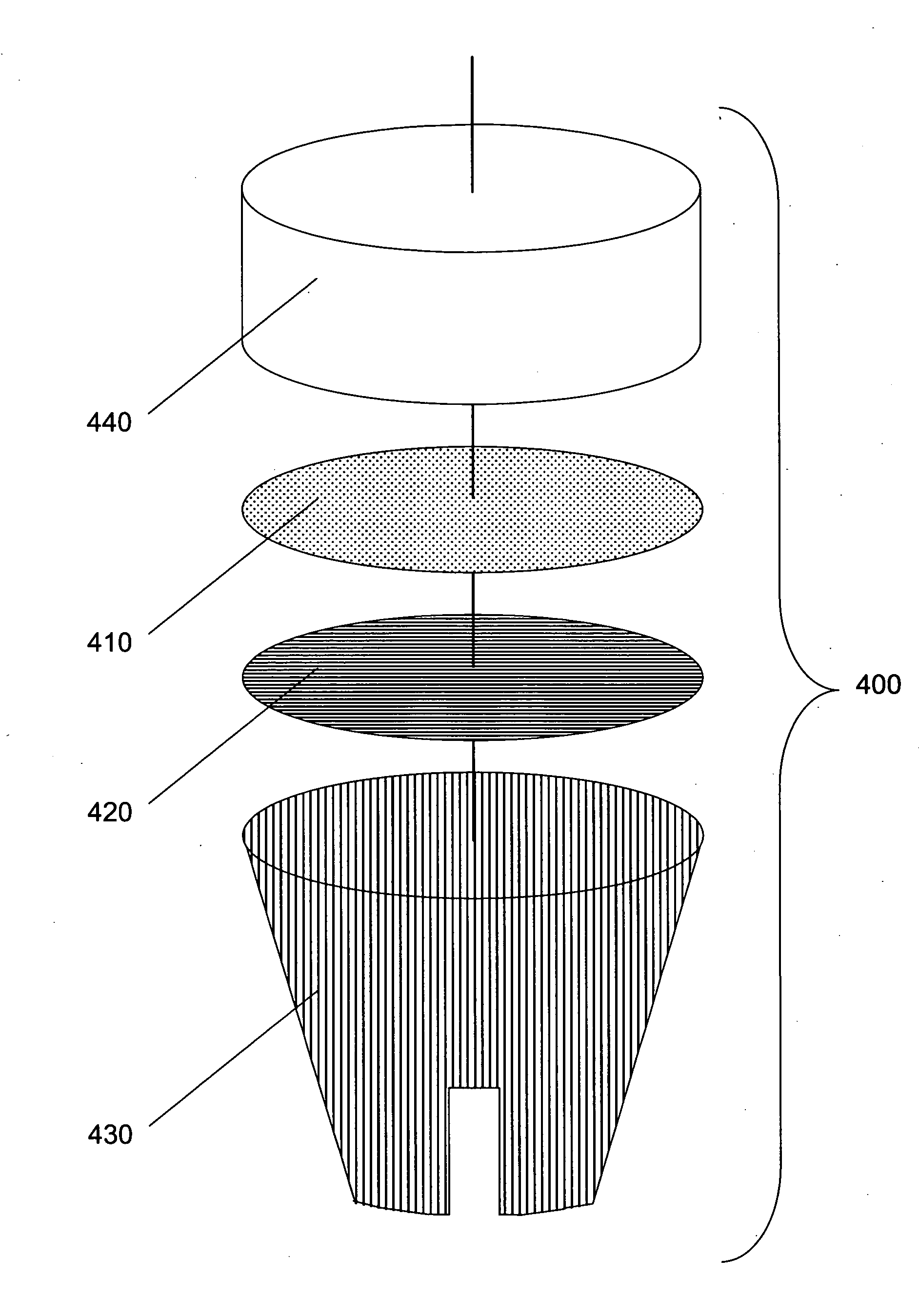
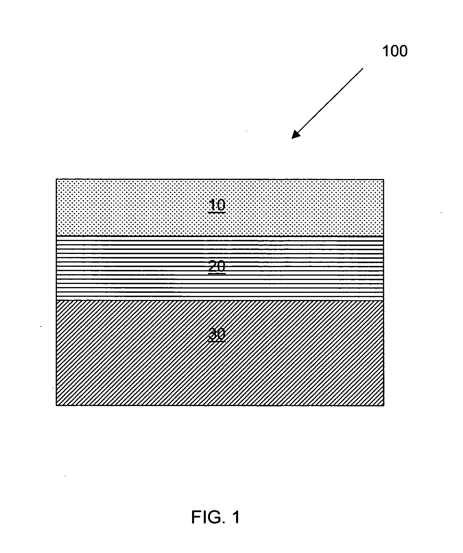
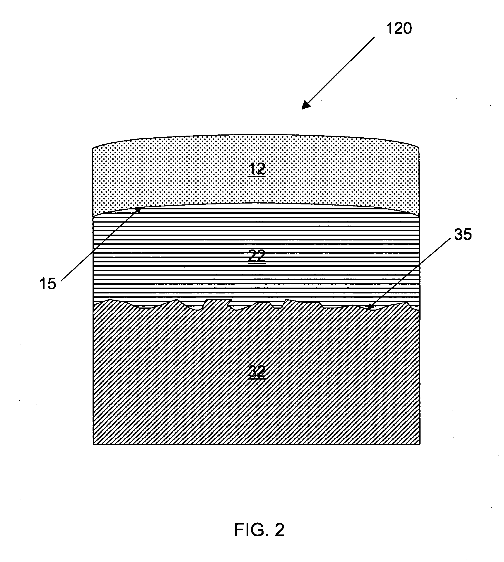
[0038]FIG. 1 shows a schematic drawing o...


PUM

PropertyMeasurementUnit
pressureaaaaaaaaaa
pressureaaaaaaaaaa
pressureaaaaaaaaaa

Abstract

A filtering device for a gravity-flow liquid treatment system includes a first filter component that can be either exposed or adjacent to a substantially transparent region in at least a portion of a filter housing. The first filter component is capable of providing a visual indication of exposure to at least one contaminant. The contaminants for which the first filter component can indicate exposure include particles, inorganic, and organic contamination. Particle contamination is indicated by a change in color of the first filter component through particle collection. Inorganic and organic contaminants are indicated by reaction with at least one agent capable of undergoing a color-change reaction in response to at least one contaminant. Water treatment systems and filtration devices that include at least one agent capable of undergoing a color-change reaction and thus give a visual indication of exposure to at least one contaminant for use in both gravity-driven and pressure-driven environments are also described.

Description

BACKGROUND OF THE INVENTION [0001] 1. Field of the Invention [0002] This invention relates to a device for filtering liquids. In particular, this invention relates to replaceable filters for use in water treatment systems. [0003] 2. Description of the Related Art [0004] Unwanted and potentially harmful contamination in water, especially drinking water, is of concern to many people. This concern creates a desire for water treatment devices in the home and elsewhere. Many water treatment devices and methods have been developed to remove or neutralize particulate and chemical contaminants. [0005] Water treatment devices are well known in the art. These devices can be employed directly in a water system, either in-line or at a terminal end, or also in self-contained batch systems. An example of an in-line system is an under-the-counter device that filters water in the source line before it reaches the faucet. Terminal end devices include countertop and faucet-mounted filtration systems....

Claims


Application Information

Patent Timeline
Patent Type & Authority Applications(United States)
IPC IPC(8): B01D35/14B01D35/143C02F1/00C02F1/28C02F1/42C02F1/44G01N21/78G01N33/18
CPCC02F1/003C02F1/283C02F1/42C02F2307/06C02F2307/02C02F2307/04C02F1/444
Inventor JOYCE, PATRICK C.LYNCH, TONI L.RINKER, EDWARD B.
Owner THE CLOROX CO
Learn More