Flow-through tank for water treatment

a technology of water treatment and flow-through tanks, which is applied in water/sewage multi-stage treatment, water softening, separation processes, etc., and can solve problems such as high cost, complicated, and potential environmental problems of water softeners, and achieves the effects of reducing the number of water softeners, and increasing the cost of water softeners

Active Publication Date: 2005-05-26
CULLIGAN INTERNATINOAL COMPANY
View PDF8 Cites 99 Cited by
  • Summary
  • Abstract
  • Description
  • Claims
  • Application Information

AI Technical Summary

Benefits of technology

[0013] In one version of this embodiment, a set of two 3-way solenoids controls the two tanks in and out of the service or treatment modes. One solenoid controls flow of service water out of a specified tank and a second directs the flow of treated water into the opposite tank. A three-way valve on the outlet of each tank provides a path

Problems solved by technology

However, such water softeners have potential environmental problems due to the high level of total dissolved solids (e.g., sodium or potassium chloride salts) discharged as waste during the regeneration process.
Moreover, as the usage of reclaimed water increases, and as water supplies become more limited, it is anticipated that usage of water softeners will be more problematic as the quality of reclaimed water is subjected to stricter regulation.
However, such alternative water treatment systems are disadvantaged in that they are typically more expensive and complicated as compared to existing water softeners.
Such peak usage demands result in water treatment systems being designed to have water treatment capacity far exceeding the actual daily usage requirements of the domicile, and consequently increased costs of typical a

Method used


Image

  • Flow-through tank for water treatment
  • Flow-through tank for water treatment
  • Flow-through tank for water treatment

Examples


Embodiment Construction

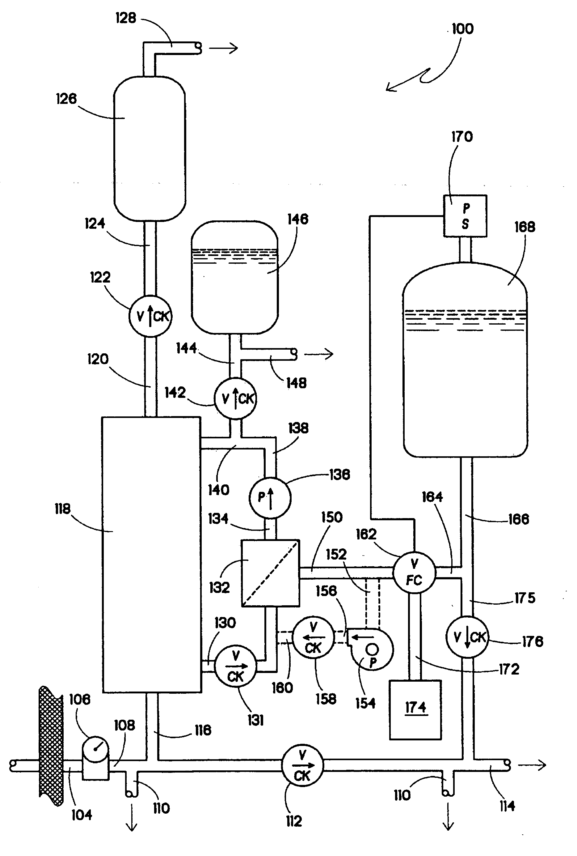
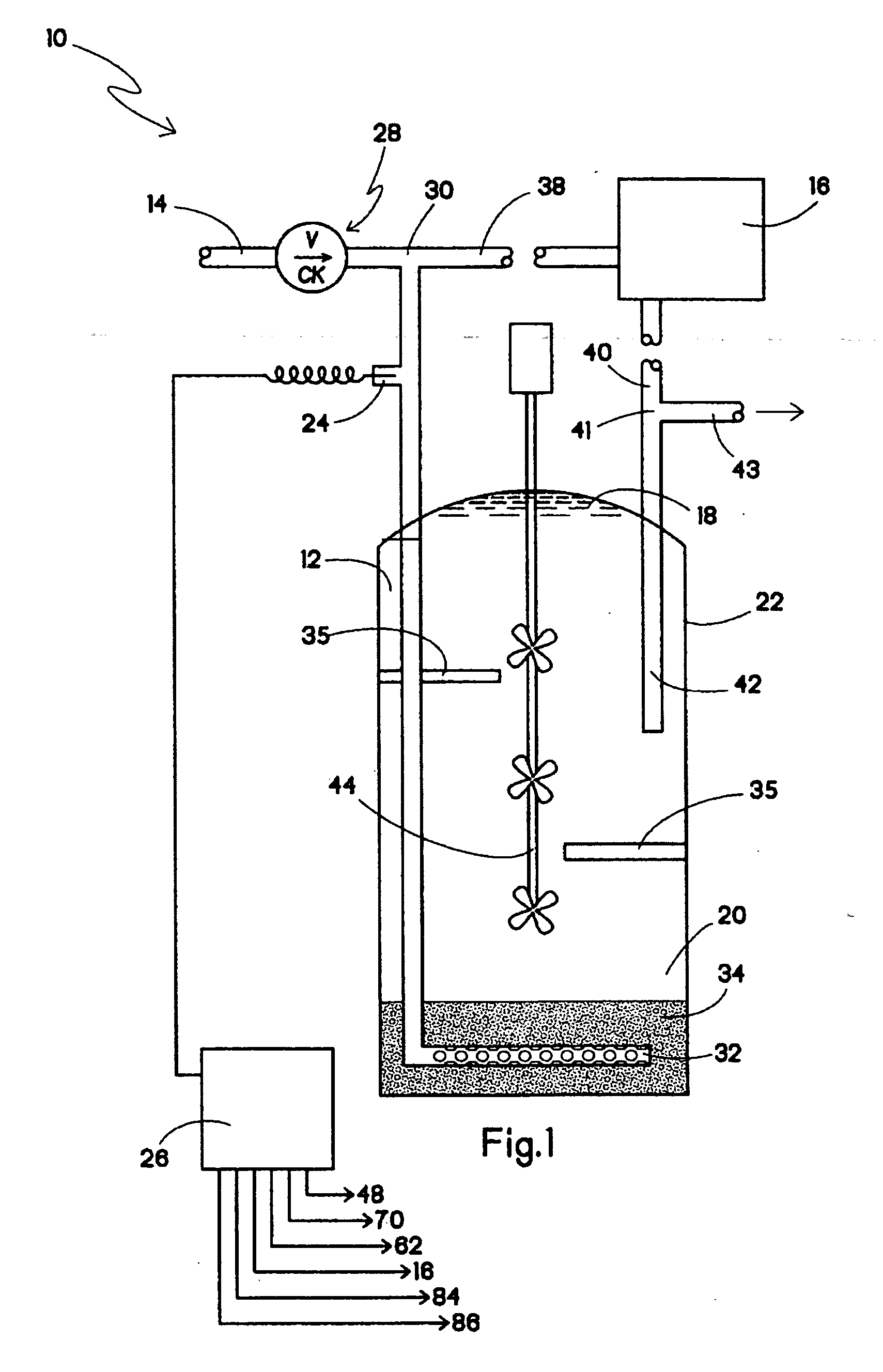
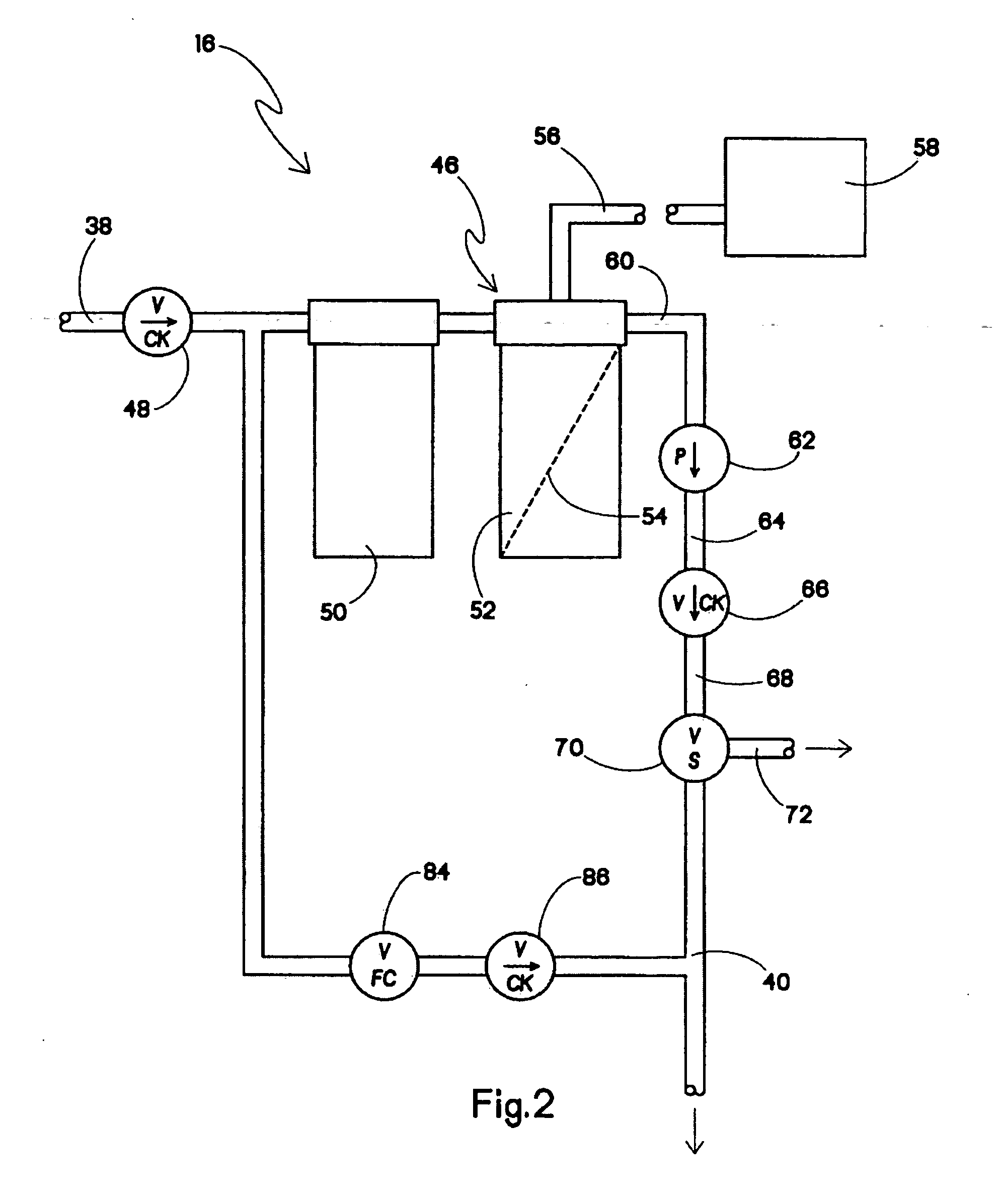
[0019] Referring now to FIG. 1, the present fluid or water treatment system, generally designated 10, includes a flow-through tank 12. The present invention, including a treatment apparatus and method of operating same, offers several advantages over the prior art. First, full and constant inlet pressure is always provided at respective points of use (i.e., treated water delivery ports). Second, water is always available at the points of use. Moreover, the present treatment system 10 is smaller and more economical compared to known non-water softener water treatment systems and devices. In addition, the present system 10 can be adapted to include an add-on storage tank for generating higher quality water, and operates with relatively simple controls.

[0020] The present flow-through tank 12 receives raw, untreated or low quality water by a line 14 that is under inlet water pressure, similar to a typical residential hot water heater. Generally, water quality is determined by a the amo...


PUM

PropertyMeasurementUnit
Pressureaaaaaaaaaa
Flow rateaaaaaaaaaa
Distributionaaaaaaaaaa

Abstract

A fluid treatment system includes at least one flow-through tank, a treatment device configured for treating at least one of an untreated fluid and a treated fluid and providing the treated fluid to the at least one flow-through tank and at least one sensing device configured for sensing the quality of fluid in the at least one flow-through tank. The sensing device is connected to the treatment device for providing the treated fluid to the at least one flow-through tank upon a determination of a quality of fluids in the at least one flow-through tank being less than or equal to a predetermined fluid quality threshold.

Description

RELATED APPLICATION [0001] This application claims priority under 35 USC§ 120 from U.S. Patent Application Ser. No. 60 / 519,872 filed Nov. 13, 2003.BACKGROUND OF THE INVENTION [0002] The present invention relates generally to fluid treatment devices such as water softeners or alternate contaminant reduction systems, and particularly to a flow-through tank water system for providing service water to points of use based upon both peak demands and daily usage in a domicile or a commercial application such as a food service establishment or other locations where water, particularly treated water is used. [0003] Self-regenerating ion exchange water softeners (hereinafter referred to as “water softeners”) are common water treatment devices used in domiciles and other facilities. Such water softeners have been preferred over alternative water treatment systems, primarily due to their low costs. However, such water softeners have potential environmental problems due to the high level of tota...

Claims


Application Information

Patent Timeline
IPC IPC(8): B01D61/08B01D61/12C02F1/00C02F1/28C02F1/42C02F1/44C02F5/00C02F5/02C02F9/00
CPCB01D61/08C02F2301/066C02F1/006C02F1/008C02F1/283C02F1/42C02F1/44C02F1/441C02F5/025C02F9/005C02F2209/005C02F2209/05C02F2209/40C02F2301/043C02F2301/046B01D61/12C02F9/20C02F2201/005B01D61/081
Inventor NEWENHIZEN, JOHN VAN
Owner CULLIGAN INTERNATINOAL COMPANY
Why Eureka
Try Eureka