Spark plug

a plug and spark technology, applied in the field of spark plugs, can solve the problems of increasing the probability of reducing the plug's ability to withstand voltage, increasing the need for new countermeasures, and reducing the wall thickness, so as to achieve the effect of increasing the operating life and high voltag

Inactive Publication Date: 2005-05-26
DENSO CORP
View PDF0 Cites 14 Cited by
  • Summary
  • Abstract
  • Description
  • Claims
  • Application Information

AI Technical Summary

Benefits of technology

[0053] With such a structure, it becomes possible to miniaturized spark plug that has

Problems solved by technology

Particularly, with an attempt to structure the spark plugs in a narrow diameter configuration as set forth above, the porcelain insulator, electrically insulating the center electrode and the metal shell from one another, results in a reduced wall thickness, causing important issu

Method used


Image

  • Spark plug
  • Spark plug
  • Spark plug

Examples


Embodiment Construction

[0062] Hereinafter, a spark plug of an embodiment according to the present invention will be described below with reference to the accompanying drawings.

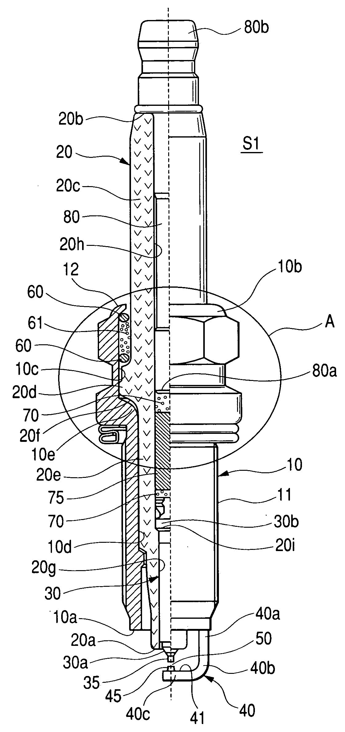
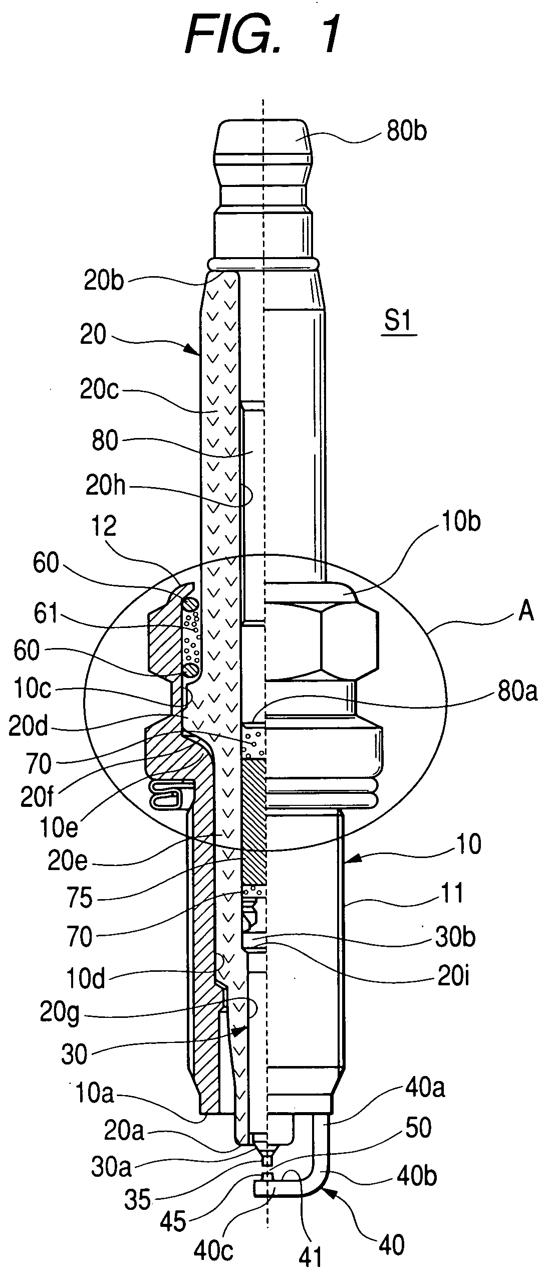
[0063]FIG. 1 is a semi-cross sectional view illustrating an overall structure of a spark plug S1 of an embodiment according to the present invention, and FIG. 2 is a semi-cross sectional view illustrating an enlarged structure of an area in proximity of an igniting section of the spark plug S1.

[0064] [Structure of Spark Plug]

[0065] The spark plug S1 is used as a spark plug for an automotive engine that includes an engine head (not shown), in which combustion chambers of the engine are defined, which is formed with threaded bores to each of which the spark plug of the presently filed embodiment is screwed in fixed place.

[0066] The spark plug S1 includes a cylindrical metal shell 10, made of electrically conductive steel (such as low carbon steel), whose outer circumferential periphery is formed with a mounting thread 11 to be scre...


PUM

PropertyMeasurementUnit
Lengthaaaaaaaaaa
Lengthaaaaaaaaaa
Timeaaaaaaaaaa

Abstract

A spark plug is disclosed as including a metal shell 10 formed with first and second bores 10c, 10d and a stepped section 10e between the first and second bores, and a porcelain insulator 20 having a largest-diameter section 20d, which is accommodated in the first bore and a small-diameter section 20e accommodated in the second bore. The first and second bores of the metal shell have a dimensional relationship, lying in a value equal to or less than 1.8 mm, which is expressed as (D1−D2)/2 where D1 represents an inner diameter of the first bore of the metal shell and D2 represents an inner diameter of the second bore of the metal shell.

Description

CROSS REFERENCE TO RELATED APPLICATIONS [0001] This application is related to Japanese Patent Application No. 2003-364161 filed on Oct. 24, 2003, the content of which is hereby incorporated by reference. BACKGROUND OF THE INVENTION [0002] 1. Field of the Invention [0003] The present invention relates to spark plugs for internal combustion engines and, more particularly, to a small-sized spark plug having a metal shell formed with a mounting thread of a value less than M10. [0004] 2. Description of the Related Art [0005] In general, the related art spark plug is known to include a metal shell formed with a mounting thread to be mounted to an engine, a porcelain insulator fixedly secured to an inside of the metal shell such that one end of the porcelain insulator protrudes from one end of the metal shell, a center electrode fixedly secured to an axial bore of the porcelain insulator such that one end of the center electrode protrudes from the one end of the porcelain insulator, and a ...

Claims


Application Information

Patent Timeline
IPC IPC(8): C22C32/00C22C5/04H01T13/20H01T13/36H01T13/39
CPCH01T13/39H01T13/20
Inventor KANAO, KEIJI
Owner DENSO CORP
Why Eureka
Try Eureka