Variable supply amplifier system

a variable supply and amplifier technology, applied in the field of electronic devices, can solve the problems of linear amplifiers, inefficient operation of amplifiers in these types of signals, and the cost of amplifiers scales with peak power, so as to optimize linearity and main amplifier efficiency, optimize linearity, and minimize bandwidth

Active Publication Date: 2005-05-26
NORTHROP GRUMMAN SYST CORP
View PDF10 Cites 167 Cited by
  • Summary
  • Abstract
  • Description
  • Claims
  • Application Information

AI Technical Summary

Benefits of technology

[0006] In accordance with one aspect of the present invention, a variable supply amplifier system is provided. A power amplifier is operative to amplify an input signal. The system delays and stores (e.g., in a digital buffer) a copy of the input signal representing a predetermined interval of time. An envelope profiler analyzes the buffered interval of the input signal and determines an appropriate supply signal pro

Problems solved by technology

The operation of amplifiers (e.g., linear amplifiers) in these types of signals is very inefficient, since the amplifiers are sized so that their supply voltage is high enough to handle the large peak voltages even though the signals are much smaller a substantial portion of the time.
Additionally, the size and cost of the power amplifier is generally proportional to the required peak output power of the amplifier.
The cost of the amplifier scales with its peak power.
Several other circuit costs including heat sinks and DC-DC power supplies scale inversely to peak power and dissipated heat (which results from the electrical inefficiency).
Related base

Method used


Image

  • Variable supply amplifier system
  • Variable supply amplifier system
  • Variable supply amplifier system

Examples


Embodiment Construction

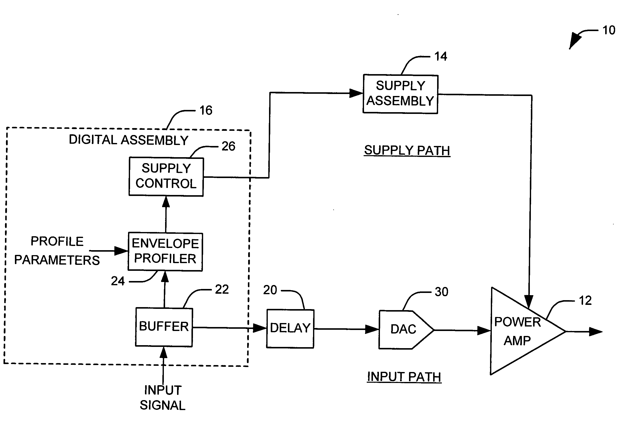
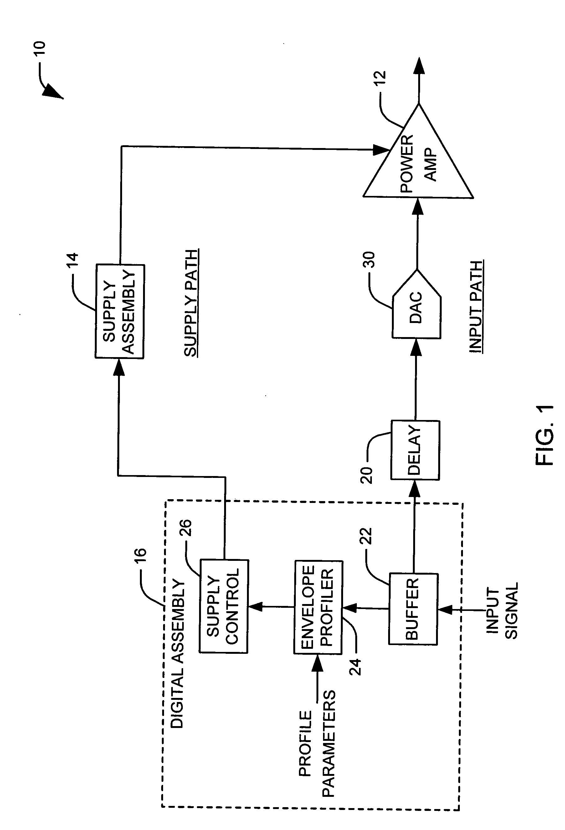
[0014] The present invention relates to a variable supply amplifier system that tracks the signal at a decreased slew rate to maintain efficient operation in the variable supply loop. The amplifier system stores a copy of an input signal within a buffer and evaluates the signal to determine a necessary amplifier supply voltage over the buffered signal portion. An amplifier supply profile is then determined that allows for efficient operation of the power amplifier while maintaining a desired slew rate. This allows the use of more efficient, low bandwidth components in the supply path, increasing the overall efficiency of the system.

[0015]FIG. 1 illustrates an amplification system or architecture 10 in accordance with an aspect of the present invention. The amplification system 10 monitors the amplitude level of a buffered interval of an input signal to determine an appropriate supply voltage profile for an associated power amplifier 12 over the buffered interval. The power amplifie...


PUM


Abstract

Systems and methods are provided for determining and providing an appropriate variable voltage supply to a power amplifier. A power amplifier is operative to amplify an input signal. A digital buffer stores a copy of the input signal representing a predetermined interval of time. An envelope profiler analyzes the buffered interval of the input signal and determines an appropriate supply signal profile for the power amplifier over the predetermined time interval. A supply control provides a supply signal according to the determined profile.

Description

TECHNICAL FIELD [0001] The present invention relates generally to electronic devices, and more particularly to a variable supply amplifier system. BACKGROUND OF THE INVENTION [0002] Modern transmitters for applications such as cellular, personal, and satellite communications employ digital modulation techniques such as quadrature phase-shift keying (QPSK) in combination with code division multiple access (CDMA) communication. Shaping of the data pulses mitigates out-of-band emissions from occurring into adjacent channels but produces time-varying envelopes. In addition to amplifying individual waveforms with time varying envelopes, many transmitters (especially in base stations) are being configured to amplify multiple carriers. Multi-carrier signals have a wide distribution of power levels resulting in a large peak-to-average ratio (PAR). The operation of amplifiers (e.g., linear amplifiers) in these types of signals is very inefficient, since the amplifiers are sized so that their...

Claims


Application Information

Patent Timeline
IPC IPC(8): H03F1/02H03F1/32
CPCH03F1/0227H03F2200/331H03F2200/102H03F1/3294
Inventor ROBINSON, IANWINTER, FRANK
Owner NORTHROP GRUMMAN SYST CORP
Why Eureka
Try Eureka