Feedforward automatic gain correction

a gain correction and automatic gain technology, applied in the direction of gain control, digital transmission, transmission, etc., can solve the problems of difficult to ensure fast response without oscillation or large distortion figure, limited filtering that can be implemented in the gain control loop, and low signal strength. the effect of reducing inter-modulation, reducing the minimum bandwidth, and quick variation of signal strength

Active Publication Date: 2013-10-15
NXP BV
View PDF5 Cites 2 Cited by
  • Summary
  • Abstract
  • Description
  • Claims
  • Application Information

AI Technical Summary

Benefits of technology

[0033]In some applications, such as car radios, the signal strength can quickly vary. This means that the minimum bandwidth of the gain determination (i.e. the cut off frequency of the low pass filter) needs to be relatively high, so that the low pass filter does not filter out these changes in signal level. However, a low cut off frequency is desired in order to reduce inter-modulation between the incoming signal and the low pass filtered signal.

Problems solved by technology

An issue with feedback circuits of this type is that the settling speed may be compromised by ensuring loop stability.
In particular, it is difficult to ensure fast response without oscillation or a large distortion figure.
The filtering that can be implemented in the gain control loop is limited by the desired response time.

Method used


Image

  • Feedforward automatic gain correction
  • Feedforward automatic gain correction
  • Feedforward automatic gain correction

Examples


Embodiment Construction

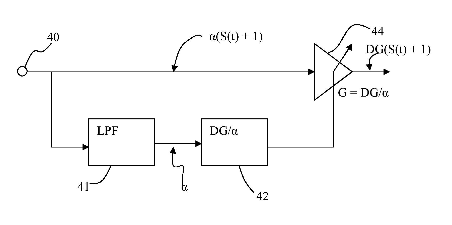
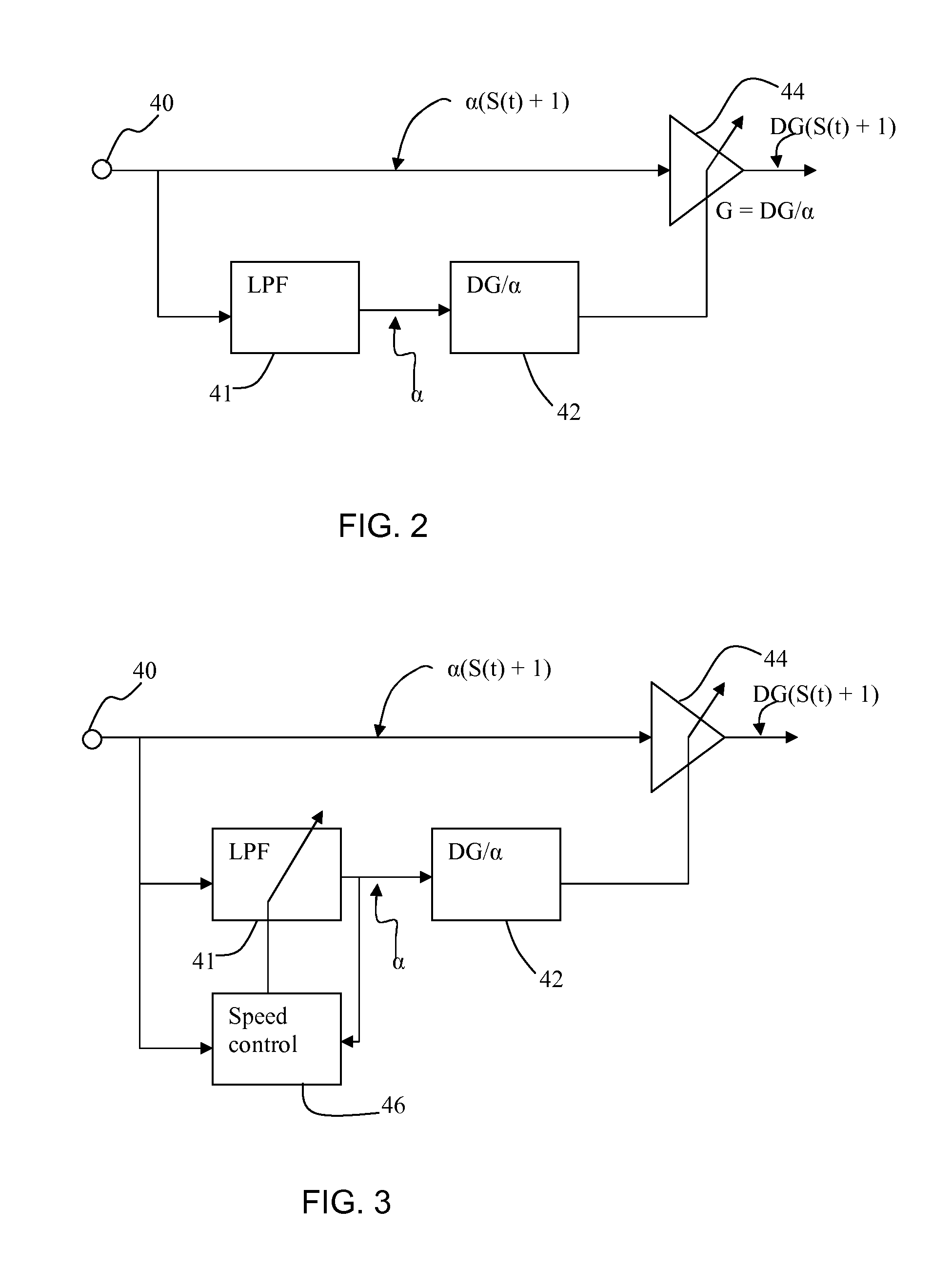
[0046]The invention provides an automatic gain control circuit for an input signal in the form of a dc reference level and a superposed (amplitude modulated) ac data signal. A feedforward AGC loop has a low pass filter for deriving the level of attenuation from the attenuated dc reference level. A multiplier value is based on the reciprocal of the level of attenuation and this multiplier enables an output signal to be generated comprising a constant multiple of the input signal.

[0047]The output signal of an AM demodulator preferably has an audio output level which is independent of the attenuation.

[0048]The input signal (which is modulated onto a radio frequency carrier of desired frequency) is given by:

T(s)=α(S(t)+1)  [1]

[0049]The value α represents the level of variable attenuation which has been suffered by the original audio signal. The original input signal comprises a dc reference level (the 1) and a superposed amplitude modulated ac data signal (the S(t)).

[0050]The value α in...


PUM


Abstract

An automatic gain control circuit is provided for an input signal in the form of a dc reference level and a superposed amplitude modulated ac data signal. A feedforward AGC loop has a low pass filter for deriving the level of attenuation from the attenuated dc reference level. A multiplier value (G) is based on the reciprocal of the level of attenuation (α) and this multiplier enables an output signal to be generated comprising a constant multiple (DG) of the input signal.

Description

[0001]This application claims the priority under 35 U.S.C. §119 of European patent application no. 10192397.7, filed on Nov. 24, 2010, the contents of which are incorporated by reference herein.FIELD OF THE INVENTION[0002]This invention relates to a feedforward automatic gain correction circuit and method, and particularly for use within an amplitude modulation system.BACKGROUND OF THE INVENTION[0003]Automatic gain correction (AGC) is used to compensate for the signal attenuation in a signal transmission path between a transmitter and a receiver, so that the receiver can provide a constant output level in the presence of this varying input signal level.[0004]Conventional AGC circuits typically employ feedback techniques.[0005]FIG. 1 of the accompanying drawings is a block schematic diagram of a simplified radio receiver and illustrates a classical radio frequency (RF) AGC system.[0006]An antenna 10 is coupled to a gain controlled RF amplifier 12. An output of the RF amplifier 12 is ...

Claims


Application Information

Patent Timeline
Patent Type & Authority Patents(United States)
IPC IPC(8): H04B1/06H04B7/00
CPCH03G3/301H03G3/3052H03G2201/202H03G2201/302H03G2201/606
Inventor PIERICK, HENK TENHULZE, GERTJAN GROOTKEUKENS, ERIK
Owner NXP BV
Why Eureka
Try Eureka