Co-Located Multi-Band Antenna

Inactive Publication Date: 2005-05-26
RAVEN ANTENNA SYST
View PDF27 Cites 14 Cited by
  • Summary
  • Abstract
  • Description
  • Claims
  • Application Information

AI Technical Summary

Benefits of technology

[0042] In a second method of phase error reduction the sub reflector 52 may be shaped. Using a sub reflector 52 roughly 9 wavelengths in size, the shaping-induced phase error may be minimized by leaving a “hole” or minima proximate the center of the main aperture illumination, as shown for example in the FIG. 5 ray-tracing diagram. For clarity, the ray diagram demonstrates only the signal path with respect to the first feed 58. By shaping the sub reflector 52 to direct most of the illuminating energy to the outer regions of the main reflector 50, there is less variation in phase across the main reflector and the aperture efficiency is improved. This is apparent from an equal-path length analysis of rays striking the main reflector center, the main reflector 50 rim, and a point midway between the center and rim: there is less path-length difference between the last two rays than there is between the first two rays.
[0061] The various embodiments of the invention create a multi-band antenna 10 with improved electrical performance and a compact form, without requiring additional measures such as FSS surfaces on the reflective surface(s) of the sub reflector 52 or the like. From the foregoing, it will be apparent that the present invention brings to the art a multiple band co-located antenna with improved performance that is compact, environmentally durable and has significant manufacturing and installation cost efficiencies. Table of Parts10antenna50main reflector52sub reflector58second radio frequency feed59waveguide launch60first radio frequency feed62aperture64third feedBfocal region

Problems solved by technology

The use of dual antennas or FSS techniques is expensive and or aesthetically unacceptable in a consumer environment.
Further, FSS surfaces may be susceptible to environmental degradation and or fouling.

Method used


Image

  • Co-Located Multi-Band Antenna
  • Co-Located Multi-Band Antenna
  • Co-Located Multi-Band Antenna

Examples


Embodiment Construction

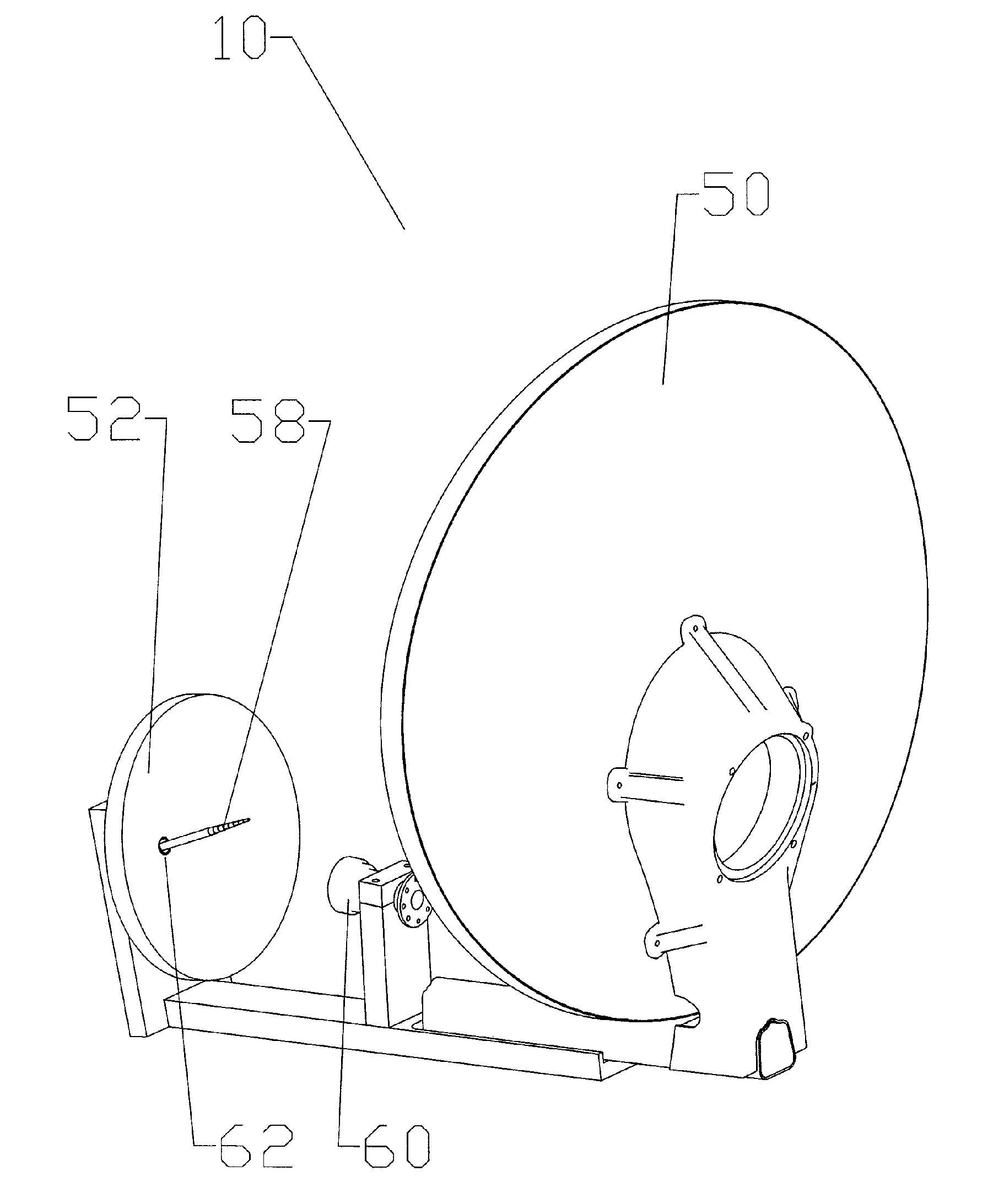
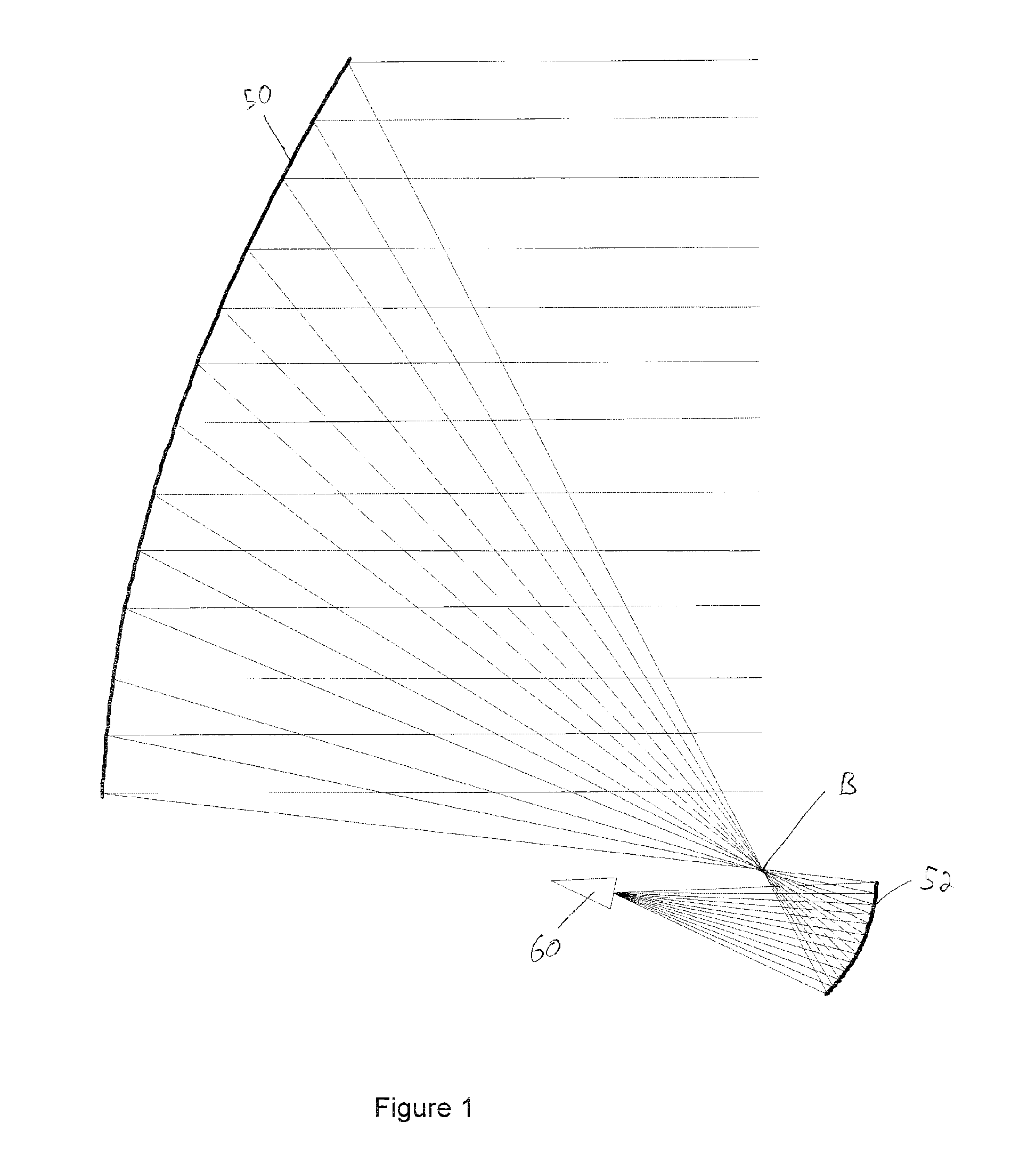
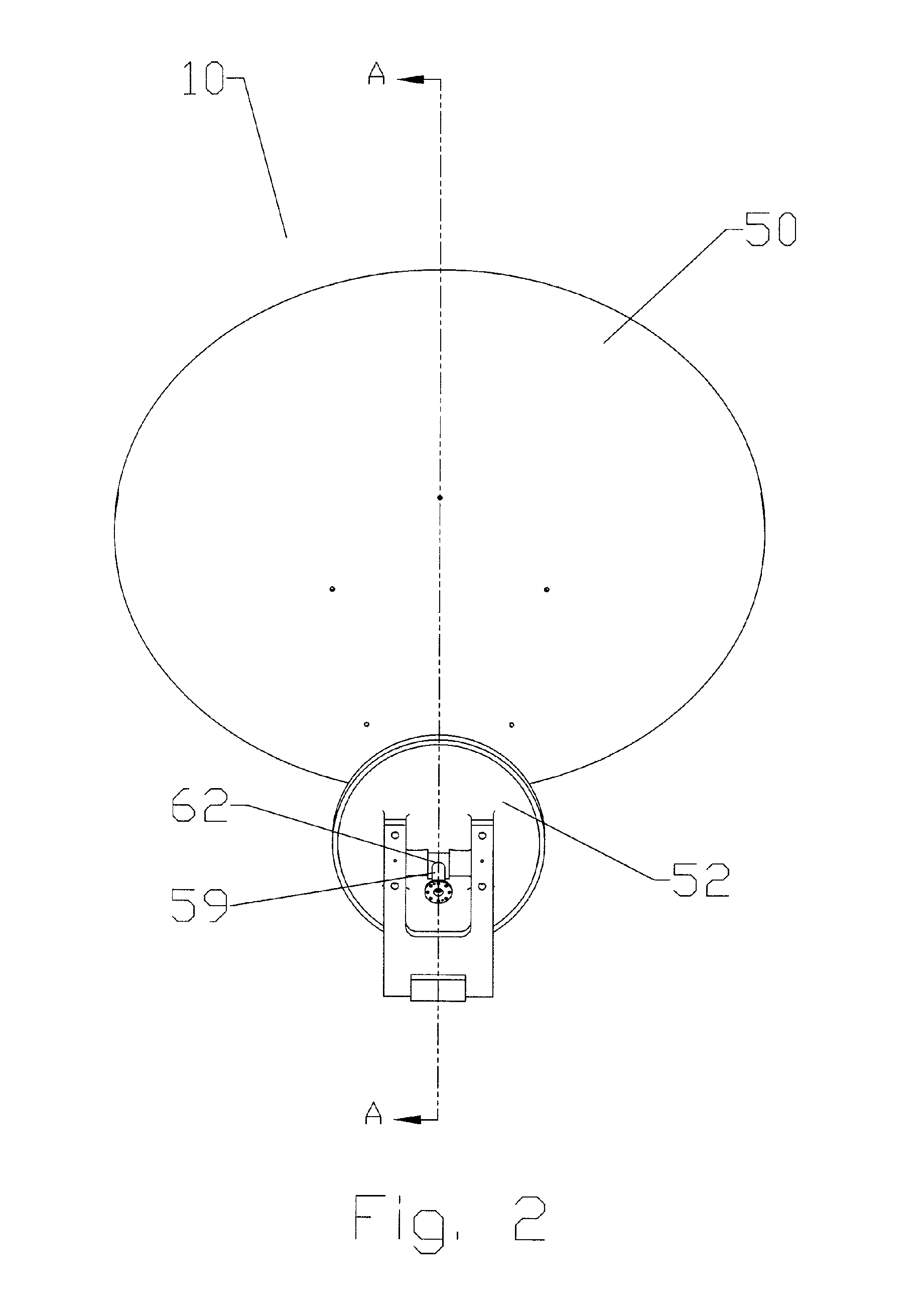
[0034] In a conventional, non-shaped Gregorian system, as shown for example in FIG. 1, the main reflector 50 is a section of a paraboloidal surface and the sub reflector 52 is a section of an ellipsoidal surface. Ray-optic analysis shows rays launched by the first feed 60 strike the sub reflector 52 to be reflected so as to pass through a single point, the focal point of the main reflector, before striking the main reflector 50 and reflecting again to form the main beam. The first feed 60 is ideally positioned at one focus of the ellipsoid-section sub reflector 52, with the sub reflector 52 positioned so that the other focus of the ellipsoid is coincident with the focal point of the main reflector 50. By stating that the main reflector 50, sub reflector 52, and first feed 60 collectively form an antenna 10 system with Gregorian optics, it is understood by those skilled in the art that these components are arranged so that the focal point or focal region of the main reflector 50 is l...


PUM


Abstract

A multi-band reflector antenna having a main reflector, a sub reflector, a first feed and a second feed. The first feed, the sub reflector and the main reflector positioned in a Gregorian optic configuration wherein an output of the first feed is directed to the sub reflector, from the sub reflector to the main reflector and from the main reflector into a first beam. The sub reflector may be shaped to distribute the output of the first feed reflecting off the sub reflector onto the main reflector whereby a central area of the main reflector has a lower illumination than a surrounding outer area of the main reflector and or elongated vertically. The second feed projecting from a hole in the sub reflector is oriented whereby an output of the second feed is directed to the main reflector and from the main reflector into a second beam.

Description

CROSS REFERENCE TO RELATED APPLICATIONS [0001] This application is a continuation-in-part of U.S. Utility application Ser. No. 10 / 484,572 filed on Jan. 22, 2004 entitled “Co-Located Antenna Design”, now pending, which is the National Stage of International Application PCT / US02 / 28991 filed on Sep. 12, 2002, entitled “Co-Located Antenna Design” which was published in English as International Publication Number WO 03 / 026173 A1 on Mar. 27, 2003; This application claims the benefit of U.S. Provisional Patent Application Ser. No. 60 / 322,343 filed on Sep. 14, 2001, entitled “Multi Beam Co-Located Antenna”. Also, This application claims the benefit of U.S. Provisional Patent Application Ser. No. 60 / 601,396 filed on Aug. 13, 2004, entitled “Co-Located Multi-Band Antenna”. U.S. Provisional patent application Ser. Nos. 60 / 322,343, 60 / 601,396 and International Application PCT / US02 / 28991 are each incorporated herein by reference in their entirety.FIELD OF THE INVENTION [0002] The field of the in...

Claims


Application Information

Patent Timeline
IPC IPC(8): H01Q5/00H01Q5/45H01Q19/17H01Q19/19
CPCH01Q19/027H01Q5/45H01Q19/192H01Q19/17
Inventor WEBB, DAVIDGEEN, DAVIDBRANDAU, RONALD J.
Owner RAVEN ANTENNA SYST
Why Eureka
Try Eureka