Digital video recorder with background transcoder

a video recorder and background technology, applied in the field of digital video recorders, can solve the problems of direct affecting the cost of units, fixed and relatively unimportant, and achieve the effects of reducing the number of video files, increasing the total computation per second of video, and reducing the size of hard disks

Inactive Publication Date: 2005-05-26
CISCO TECH INC
View PDF4 Cites 34 Cited by
  • Summary
  • Abstract
  • Description
  • Claims
  • Application Information

AI Technical Summary

Benefits of technology

[0027] The present invention provides a way to employ the advantages of an advanced video codec like H.264 within the real-time constraints of a digital video recorder for recording live broadcast television. The key feature of the invention is a transcoding operation that takes previously compressed video (typically MPEG-2) and compresses it to a smaller size. This operation takes its input from a file and puts its output to a file on a hard-disk, and so is not constrained by the rate of incoming video. This allows the transcode algorithm to use the finite computational resources over a longer period of time, thereby providing greater total computation per second of video. In an exemplary embodiment, the computational power is used to perform the more demanding video compression algorithm of H.264, resulting in a smaller file. Other sophisticated compression algorithms may also be used as desired. The original, larger file is deleted, allowing more room for more video in a given hard-disk.
[0028] In practice, the transcoding stage will often take place overnight, or on other off-hours when the DVR is neither recording nor playing back video. In computer terminology this is called a background task. This feature allows a DVR to be implemented with fewer hardware computing resources than one that must record, playback, and transcode simultaneously. In other words, the transcoding stage uses the DVR's hardware resources at a time when they are not otherwise employed. This aspect of the invention takes advantage of the fact that the average viewer will only record or watch 5 hours of video a day, yet the DVR is powered and available 24 hours a day.
[0029] In addition, the invention provides a way for digital set-top box that includes a DVR to take advantage of advanced video compression technology. In a digital STB, the programs come into the box already compressed into MPEG-2 format. (The providers cannot switch to H.264 at the head-end. Because of their installed based of STBs, digital satellite and digital cable providers must continue to provide all of their programs in the MPEG-2 format.) With this invention, the STB can convert recorded programs into a more compact format like H.264, and thus provide more total recording space for the user.

Problems solved by technology

However a main disadvantage of a hard-disk is its fixed size, as compared to a removable storage medium such as a VCR tape.
(Audio is assumed to be compressed and stored as well, but audio is an order-of-magnitude smaller than video and, therefore, relatively unimportant.)
Today different models are offered with different size hard disks, which directly affect the cost of the units.
It is relatively hard to improve the video compression rate.
This complexity directly affects the cost of implementing an encoder.
Unfortunately, there are several obstacles that make a real-time H.264 encoding system very expensive: The high computational resources needed to do H.264 encoding in real-time; The large amount of memory required to do H.264 encoding in real-time; The rate at which H.264 encoding proceeds is highly variable, necessitating a large buffer for uncompressed video data; Still another drawback to using a real-time H.264 is the increased latency for the video to pass through the encoder-decoder chain before being displayed on the TV set.
However, such a tool is not applicable to a DVR system, which is a consumer device that is constrained to operate on real-time video input and to provide real-time video output.

Method used


Image

  • Digital video recorder with background transcoder
  • Digital video recorder with background transcoder
  • Digital video recorder with background transcoder

Examples


first exemplary embodiment

[0044] A first exemplary embodiment of the invention is a stand-alone Digital Video Recorder (DVR) unit for home use. It is an improvement on the prior art just described. This unit is intended to provide a maximum amount of video storage, measured in hours, at a low price. To this aim, the DVR unit is described herein with just the fundamental features of a “personal” video recorder; it is assumed that many other features, such as an electronic programming guide, could be included in such a product, depending on the final price range of the unit.

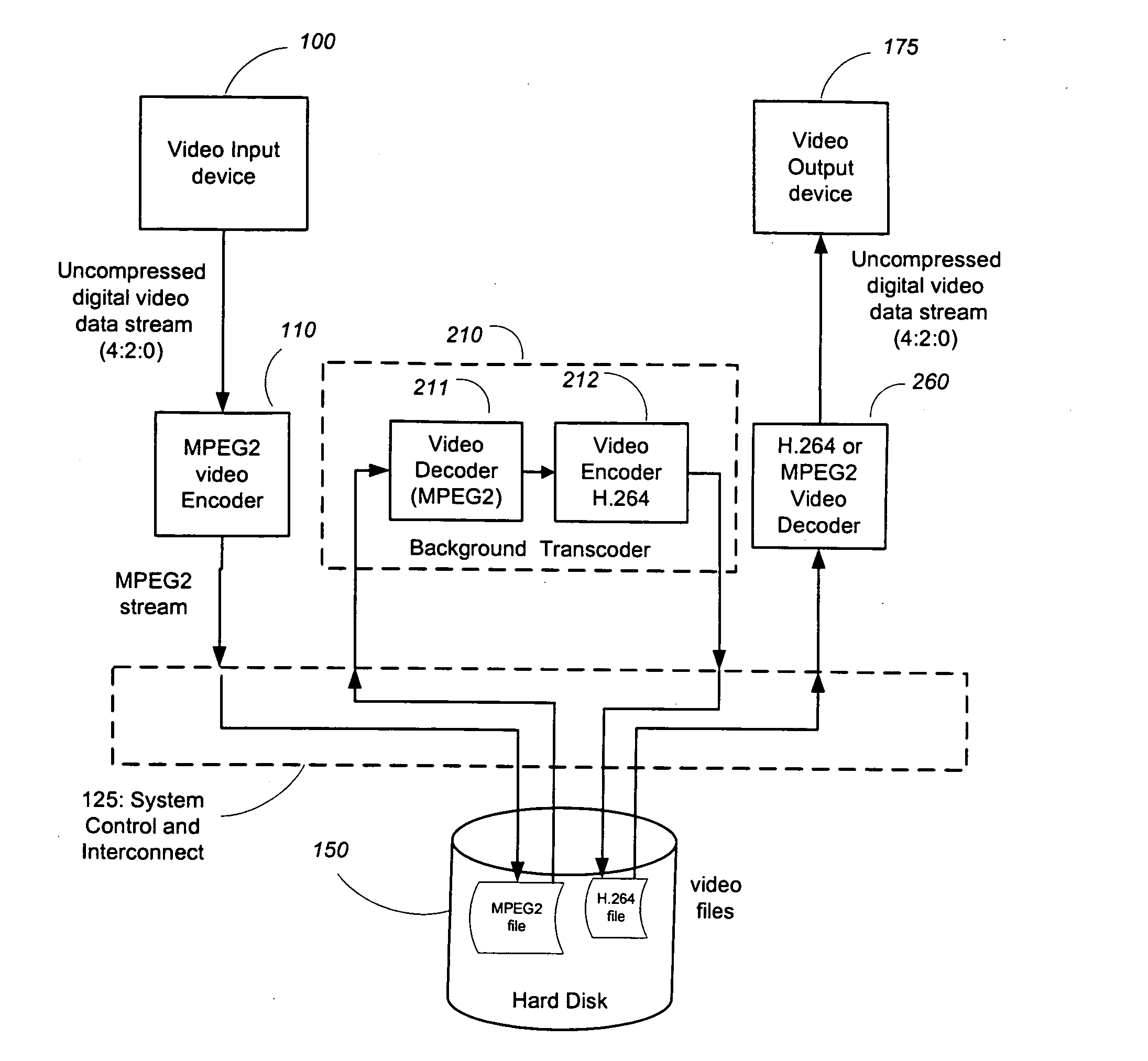
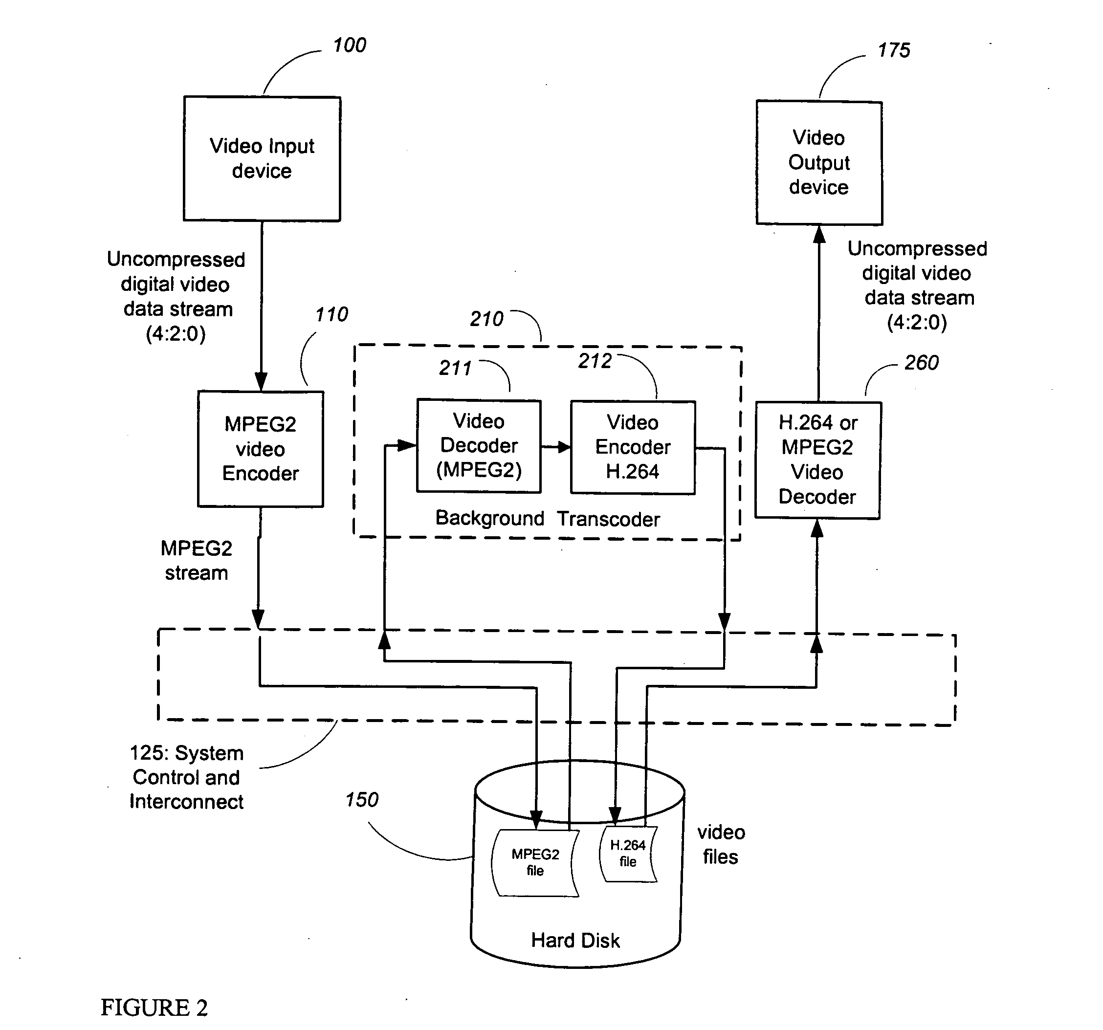
[0045]FIG. 2 is a block schematic showing the data flow through the stages of the first exemplary embodiment. As illustrated, television signals enter the system from live broadcast through the video input device 100, which typically includes a TV tuner and an NTSC decoder. The video input device 100 provides uncompressed digital video to the first video encoder (e.g., MPEG-2 encoder) 110. The first video encoder 110 compresses the video t...

first embodiment

Flow Chart of Operation (First Embodiment)

[0052]FIG. 3 illustrates the sequence of events that occur in the DVR system of FIG. 2. As is now conventional for VCRs and DVRs, the system is programmed by the user to record television shows at prescribed times. Accordingly, at step 301, the user specifies the time and channel of the show, either directly (using a remote control and an on-screen menu) or indirectly (by identifying the show by name on an on-screen program guide). At the prescribed time, the DVR tunes the tuner to the prescribed television channel and begins the recording process (step 302). The video encoder 110 compresses the incoming video to MPEG-2 in a conventional manner using the video processing resources to provide a first compression (1) at step 303. The compressed video (1) is written to the hard-disk 150 at step 304 as soon as it is generated. Recording proceeds until the video program ends. The user can select to playback the file at anytime, even while it is b...

second exemplary embodiment

[0054] A second exemplary embodiment includes a digital set-top box (STB) with a built-in hard-disk for video recording in accordance with the techniques of the invention. In such an embodiment, the STB receives a signal that is already compressed into MPEG-2. Because of this, DVR functionality can be added to a STB in a straightforward way. Indeed, most of the DVRs that are available today are built into STBs for either digital-cable or digital-satellite television services. Such a box does not require a video encoder, since the signal is already MPEG-2. This both lowers the price and increases the quality of the DVR recording. This increased quality comes from the fact that the MPEG-2 encoders used at the head-end of the cable or satellite delivery system are very expensive and of very high quality. They achieve a very low bit-rate (compared to consumer MPEG-2 encoders) and a good picture quality.

[0055] Still, it could be desirable to lower the bit-rate even further for the purpo...


PUM


Abstract

A Digital Video Recorder is used to record broadcast television programs, store them on a hard disk, and replay them for later viewing. The programs are compressed in the MPEG-2 video compression format when they are first stored on the disk. A separate, second compression algorithm is later performed on the video files that are on the disk. Such transcoding typically occurs when the Digital Video Recorder is otherwise inactive and is used to apply more compression to the stored programs. This step results in a smaller file size for each video file and thereby permits more hours of video to be stored on a given hard disk.

Description

FIELD OF THE INVENTION [0001] The present invention relates to a digital video recorder that receives and digitally stores television programs for subsequent playback by the user. BACKGROUND OF THE INVENTION [0002] The Video Cassette Recorder (VCR) has been popular in homes to record broadcast television shows for later viewing. Recently, the Digital Video Recorder (DVR) (sometimes also called Personal Video Recorder or PVR) has appeared and will probably eventually replace the VCR. For a detailed description of the operation of a typical DVR, see U.S. Pat. No. 6,233,389. While digital video recorders also exist that use tape or removable disks for storage, the popular DVR uses a hard-disk as the mass storage device for the recorded broadcast television signals. [0003] The fixed hard-disk medium has several advantages for recording broadcast television. It is both high capacity and random-access. These features allow it to hold a great number of recorded TV programs and to allow ins...

Claims


Application Information

Patent Timeline
Patent Type & Authority Applications(United States)
IPC IPC(8): H04N5/76H04N5/781H04N9/804
CPCH04N9/8042H04N5/781
Inventor FRIEL, JOSEPH T.MAUCHLY, J. WILLIAMWEIR, ANDREW P.
Owner CISCO TECH INC
Why Eureka
Try Eureka