
Method and apparatus for underground pipeline installation

Inactive Publication Date: 2005-05-26
EARTH TOOL L L C
View PDF7 Cites 16 Cited by
  • Summary
  • Abstract
  • Description
  • Claims
  • Application Information

AI Technical Summary

Benefits of technology

[0023] In this method, it can be seen that there was no excavation at the manhole, only a small amount of work in the manhole to grout the opening created by the burst head. When manholes are located at busy urban intersections (a very common placement for a manhole), the adjacent pipes can now be replaced with stout, desirable DIP. Using the enhanced MEw / oE process with no excavation at the manhole, the insertion pit can be placed strategically somewhere mid block, minimizing impedance of traffic flow. Minimizing the total amount of excavation and all with a method that has been is widely accepted for use with HDPE product pipe. This revised method allows an alternate pipe style to be used with a small incremental amount of effort in the insertion pit.

Problems solved by technology

While this unit is overly capable in that it has 57.5 tons of thrust available and is also capable to rotating a high torque auger flighting, it does demonstrate existing devices that are adaptable for the new application.

Method used


Image

  • Method and apparatus for underground pipeline installation
  • Method and apparatus for underground pipeline installation
  • Method and apparatus for underground pipeline installation

Examples


Embodiment Construction

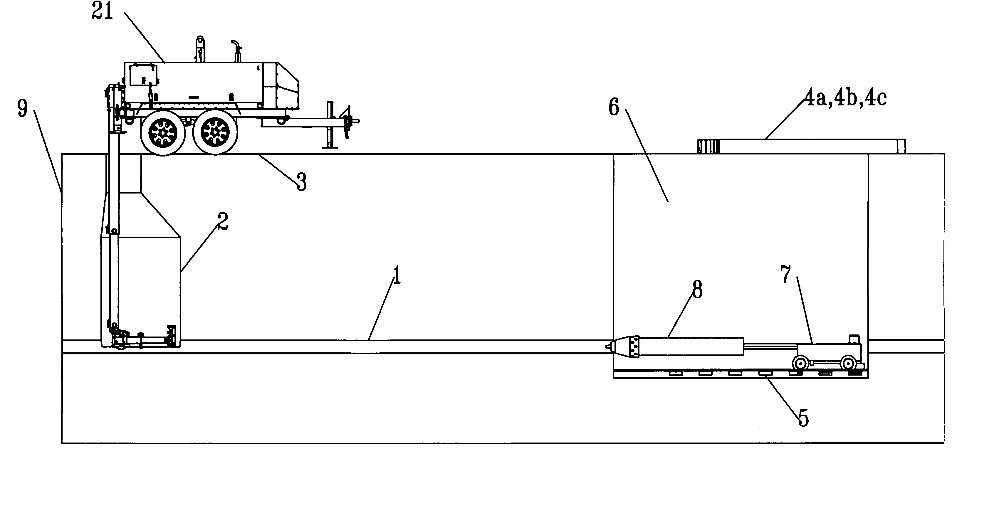
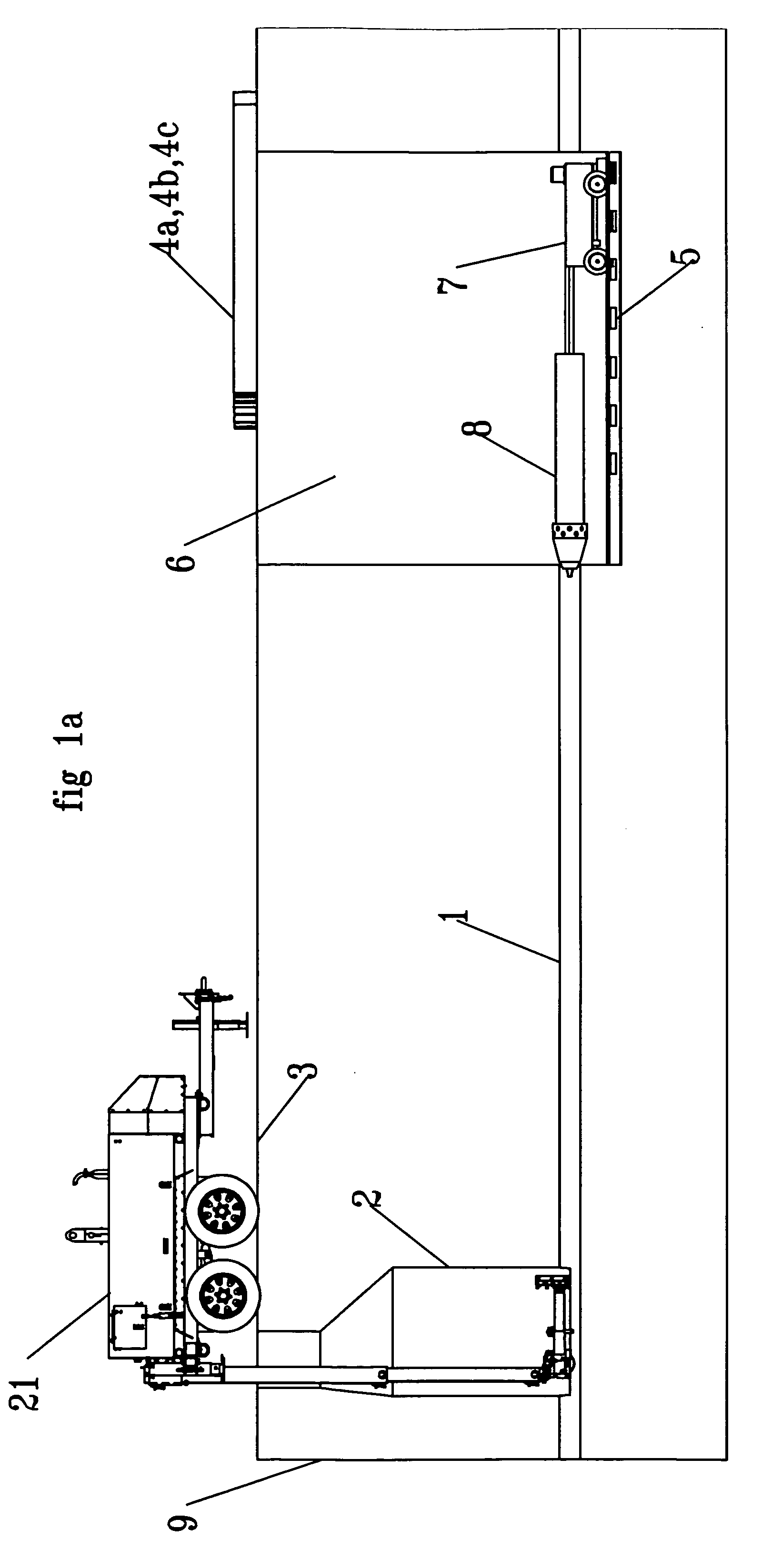
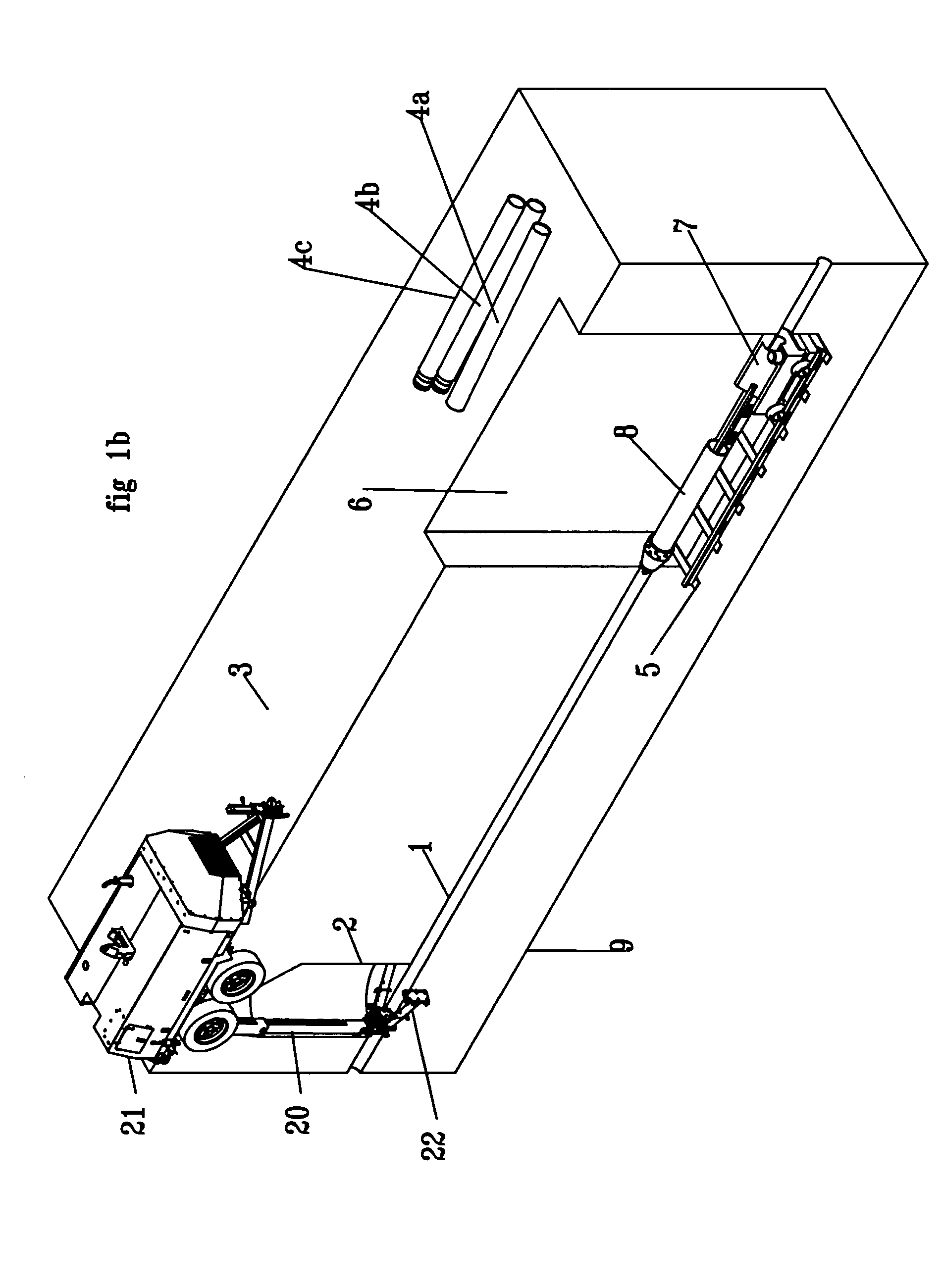
[0024]FIG. 1b shows an isometric overhead view of a jobsite. An existing pipeline 1, 8 inches in diameter runs 10 feet below the ground surface 3. The soil mass 9 surrounding the system which is rectangular in shape for illustration is actually infinite in all directions other than up. This pipeline 1 exists to conduct sanitary sewer flow to and through access manhole 2. Pipeline 1 should be assumed as needing replacement due to its age and state of decay. Excavation 6 is an insertion pit just over 13 feet long. It is shown abnormally close to manhole 2. Shown with just 25 feet between pit 6 and manhole 2 for clarity in this illustration, a more typical distance would be 100 to 500 feet.

[0025] Further, the jobsite shown in FIG. 1b is sectioned vertically along a plane that bisects the center of the existing or host pipe 1. Pipes 4a, 4b and 4c are setting on the ground surface adjacent to the insertion pit 6, note that pipes 4b and 4c have genders such that they can be connected end...


PUM


Abstract

A method according to the invention for installing an underground pipe uses a ground piercing tool having an elongated tubular tool body, a striker disposed for reciprocation within an internal chamber of the body to impart impacts to an impact surface for driving the tool forwardly through the ground, and an expander having a diameter greater than that of the tool body. The method includes the steps of securing a tubular shroud to the expander so that the ground piercing tool is disposed inside of the shroud, operating the tool in forward mode over a run so that the impact tool and shroud move forward, fitting a front end of a replacement pipe into sliding engagement with a rear end of the shroud, and pushing the replacement pipe from a rear end portion thereof in a manner sufficient to insure that a front end of the replacement pipe remains in sliding contact with the shroud as the tool moves forward.

Description

[0001] This application claims priority of U.S. Provisional Patent Application Ser. No. 60 / 524,590, filed Nov. 25, 2003.FIELD OF THE INVENTION [0002] The present invention relates to underground pipe bursting and replacement, especially using a pneumatic impact tool. BACKGROUND OF THE INVENTION [0003] The method of installing pipe through a process known as pipe bursting is well known in the industry (see Streatfield et al U.S. Pat. Nos. 4,738,565; 4,720,211; 4,505,302). The host pipe may be any that is frangible in nature. These host pipes (pipe that is already in the ground) are very suitable for fracture with a pneumatic impact device such as the Hammerhead Mole®. Further, it is common for manufacturers of these pneumatic devices to teach the method outlined in Wentworth (U.S. Pat. No. 6,299,382) of Manhole Extraction without Excavation, hereafter MEw / oE. [0004] The new pipe, most often referred to as the product pipe, is widely preferred to be HDPE (High Density Poly Ethylene). ...

Claims


Application Information

Patent Timeline
IPC IPC(8): E21B7/20F16L55/165
CPCF16L55/1658E21B7/206
Inventor WENTWORTH, STEVEN W.CRANE, ROBERT F.
Owner EARTH TOOL L L C
Learn More