Eureka AIR delivers breakthrough ideas for toughest innovation challenges, trusted by R&D personnel around the world.

Flow monitoring apparatus having an ultrasonic sensor with a coupling adapter having securing mechanism

a technology of ultrasonic sensor and coupling adapter, which is applied in the direction of sound producing device, liquid/fluent solid measurement, using ultrasonic/ultrasonic/infrasonic waves, etc. it can solve the problem of large back-reflected fraction, in-out-coupling of ultrasonic measuring signals is especially problematic, etc. problem, to achieve the effect of improving signal/noise ratio and increasing the measuring accuracy of the clamp-on flow measuring devi

Inactive Publication Date: 2011-11-01
ENDRESS HAUSER FLOWTEC AG
View PDF21 Cites 11 Cited by
  • Summary
  • Abstract
  • Description
  • Claims
  • Application Information

AI Technical Summary

Benefits of technology

[0012]An object of the invention is to provide a cost-effective, efficient, clamp-on, flow measuring device, which is simple to mount on a pipeline.
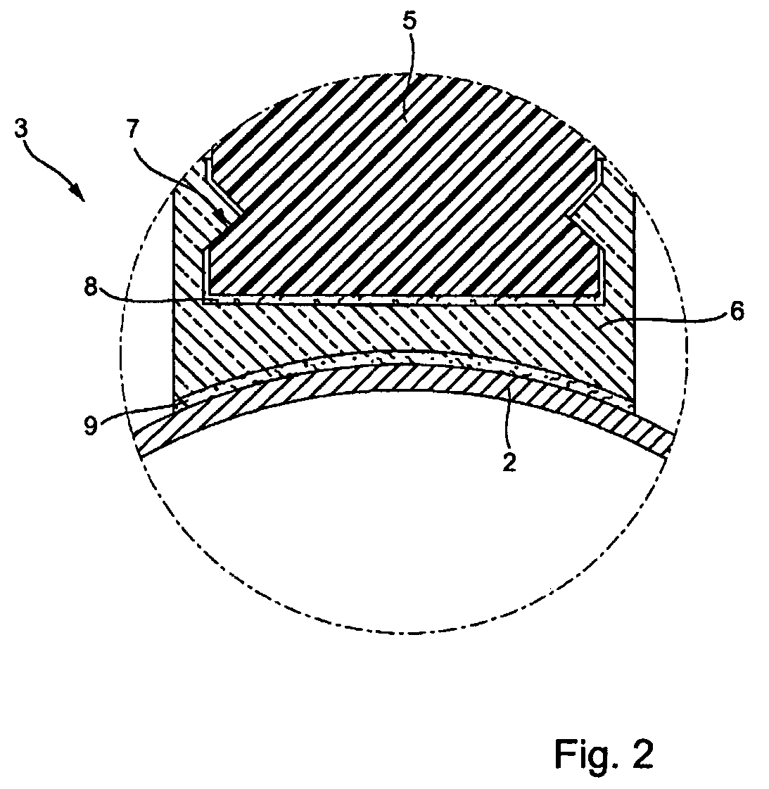
[0014]Preferably, the securement mechanism is a snapping / plug-in mechanism. Such mechanisms permit an easy mounting of the coupling adapter to the coupling shoe. Of course, also any other usual type of securement is applicable in connection with the solution of the invention. For example, it is possible to screw the coupling adapter to the coupling shoe.
[0016]In an advantageous further development of the apparatus of the invention, there is provided between the coupling shoe and the coupling adapter a first layer of a coupling medium. Beyond that, an option is to arrange a second layer of coupling medium between the coupling adapter and the pipeline. The two layers serve for minimizing impedance jump between mutually bordering media.
[0021]Especially, the coupling adapter is so embodied as a function of the material and / or the geometry of the pipe wall, that reflection of the ultrasonic measuring signals upon in-coupling into the pipeline, or upon out-coupling out of the pipeline, is approximately zero, or minimal. In a first embodiment of the apparatus of the invention, it is provided that thickness of the coupling adapter and wall of the pipeline are so selected, that they are optimally matched to the wavelength of the ultrasonic measuring signals. In principle, the thickness of coupling adapter and tube wall depends on material—here, especially, the E-modulus, density and Poisson's ratio of the material—on wavelength, or frequency, of the ultrasonic measuring signals and on the angle of incidence / emergence, at which the ultrasonic measuring signals are radiated through the wall, into the pipeline, or out of the pipeline, as the case may be. It has been found, that thickness of the coupling adapter and wall of the pipeline should be at least three times the wavelength of the ultrasonic measuring signals. If the material is, for example, steel, with a transverse sound velocity of 3200 m / sec, and if the ultrasonic measuring signals have a wavelength of 1.6 mm, then it is preferred to make coupling adapter and the wall of the pipeline at least 4.8 mm thick. In this way, it is assured that only a minimized fraction of the ultrasonic measuring signals propagate in the wall of the pipeline. An alternative embodiment, which likewise impedes the development of transverse waves in the wall of the pipeline, provides that the coupling adapter is so embodied that attenuation of the ultrasonic measuring signals is minimized in the coupling adapter. For this, the coupling adapter and / or an attenuation layer matched to the dimensions of the pipeline are / is so embodied that sound waves arising in the wall of the pipeline are immediately attenuated. Especially, the attenuation results from penetrations or cavities in the coupling adapter or in the attenuation layer. Supplementally or alternatively, there are incorporated in the material of the coupling adapter or the attenuation layer, at least in selected regions, particles having an attenuating function. Such particles are, for example, particles of tungsten oxide. By the above-described embodiments, signal / noise ratio is improved and, thus, the measuring accuracy of the clamp-on flow measuring device is increased.

Problems solved by technology

Thus, use of such ultrasonic flow measuring devices is quite strongly limited, in comparison to ultrasonic flow measuring devices working e.g. according to the travel-time difference principle.
In- and out-coupling of the ultrasonic measuring signals is especially problematic, when the pipeline is manufactured of metal and a gaseous medium is flowing in the pipeline.
The back-reflected fraction is so large, that no reliable flow measurement is possible with a conventional ultrasonic sensor.
If, then, yet other sources of error arise, which relate, for example, to the installation and mounting or to changes of environmental conditions, then a conventional ultrasonic flow measuring device is unsuitable for the particular application.

Method used


Image

  • Flow monitoring apparatus having an ultrasonic sensor with a coupling adapter having securing mechanism
  • Flow monitoring apparatus having an ultrasonic sensor with a coupling adapter having securing mechanism
  • Flow monitoring apparatus having an ultrasonic sensor with a coupling adapter having securing mechanism

Examples


Embodiment Construction

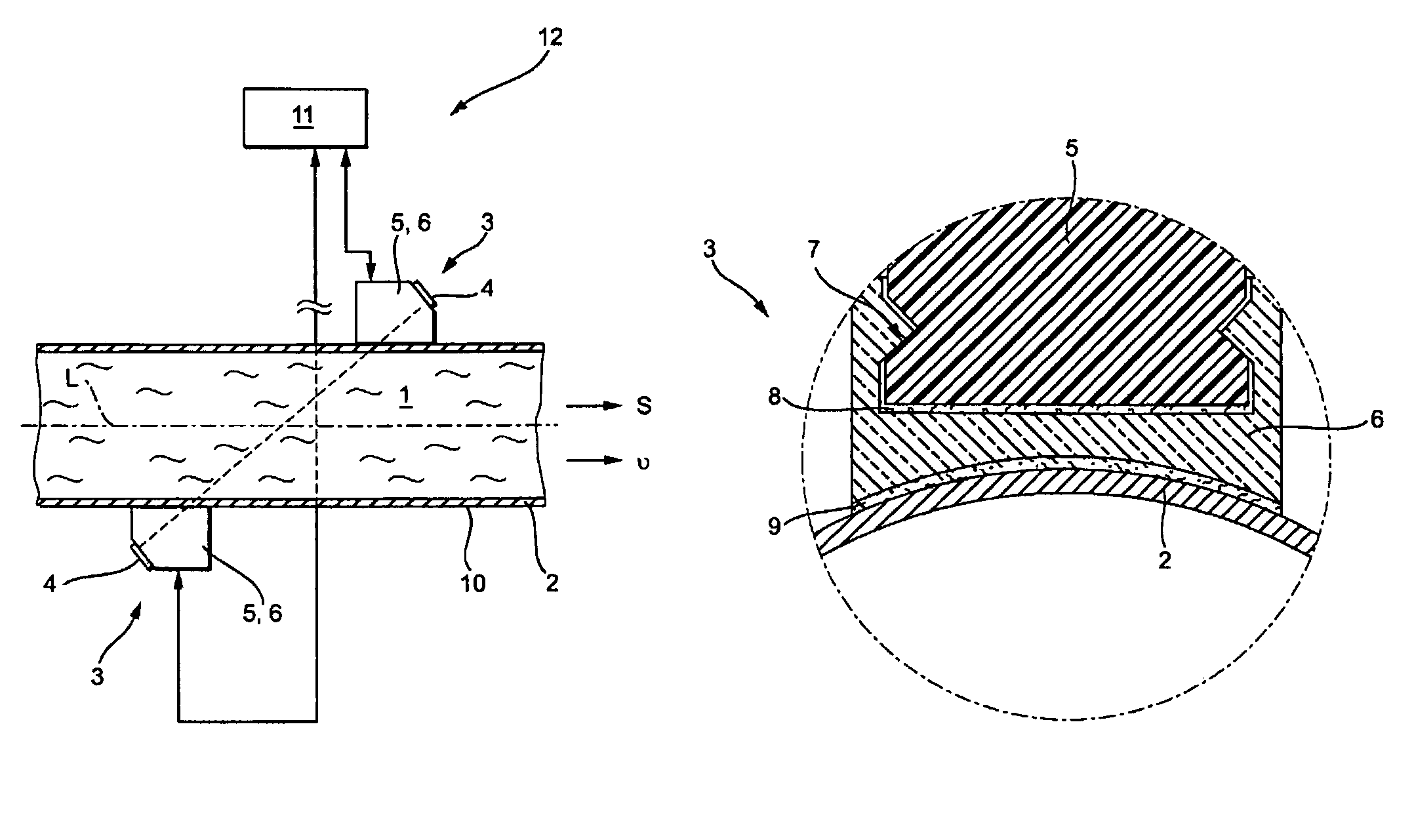
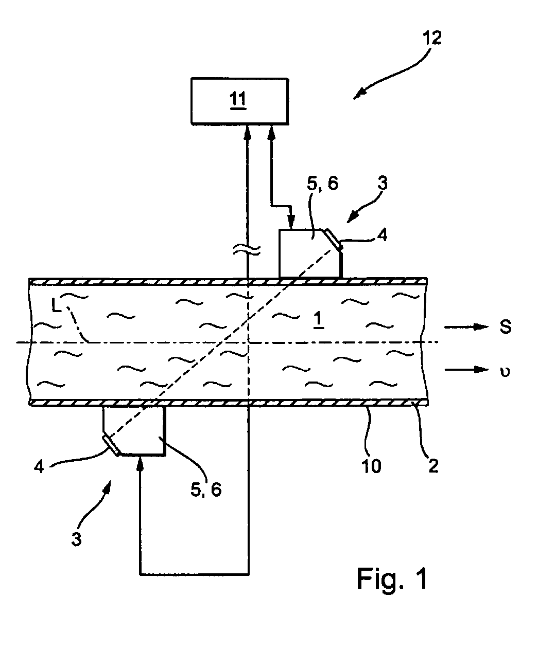
[0029]FIG. 1 shows a schematic drawing of a clamp-on flow measuring device 12 of the invention with two ultrasonic sensors 3. The illustrated flow measuring device 12 ascertains volume flow, or mass flow, of the medium 1 flowing in the pipeline 2 using a sound entrainment method, especially the known travel-time difference method.

[0030]Essential components of the clamp-on ultrasonic flow measuring device 12 are the two, already mentioned, ultrasonic sensors 3 and the control / evaluation unit 11. The two ultrasonic sensors 3 are applied to the wall 10 of the pipeline 2 by means of a securement apparatus not shown specially in the figures. Appropriate securement mechanisms are sufficiently known from the state of the art and are available from, among others, the present assignee. Medium 1 flows through the pipeline 2 of inner diameter d and outer diameter D in the stream direction S with the flow velocity v.

[0031]The ultrasonic sensor 3 of the invention includes as an essential compone...


PUM


Abstract

An apparatus for ascertaining, and / or monitoring, volume-or mass-flow of a medium flowing through a pipeline in the direction of the longitudinal axis of the pipeline. The apparatus includes: at least one ultrasonic sensor, which radiates / receives ultrasonic measuring signals at an angle of incidence / emergence into / out-of the pipeline; and a control / evaluation unit which provides, based on the ultrasonic measuring signals, information concerning volume- and / or mass-flow of the medium through the pipeline. The ultrasonic sensor includes at least one sound-producing element, a coupling shoe and a coupling adapter. The end region of the coupling adapter facing the coupling shoe has a securement mechanism for releasable securement of the coupling adapter to the coupling shoe. The end region of the coupling adapter facing the pipeline is embodied as a function of the pipeline in such a manner that it is form-fittingly securable to the pipeline.

Description

TECHNICAL FIELD[0001]The invention relates to a clamp-on, ultrasonic, flow measuring device for ascertaining and / or monitoring volume- or mass-flow of a medium flowing through a pipeline in the direction of the longitudinal axis of the pipeline.BACKGROUND DISCUSSION[0002]Such a device includes: at least one ultrasonic sensor, which radiates into, or receives from, the pipeline ultrasonic measuring signals at angles of incidence and emergence, respectively; and a control / evaluation unit, which ascertains, on the basis of the ultrasonic measuring signals, volume- and / or mass-flow of the medium through the pipeline.[0003]Ultrasonic flow measuring devices of the above-described kind are used often in process- and automation-technology. They make possible contactless ascertainment of volume- and / or mass-flow of a medium in a pipeline. Clamp-on flow measuring devices working according to the travel-time difference method are described, for example, in EP 0 686 255 B1, U.S. Pat. No. 4,484,...

Claims


Application Information

Patent Timeline
IPC IPC(8): G01F1/66G01R33/20
CPCG01F1/662G01F1/667G10K11/004
Inventor BERBERIG, OLIVERBERGER, ANDREASOUDOIRE, PATRICKWIEST, ACHIM
Owner ENDRESS HAUSER FLOWTEC AG
Why Eureka
Eureka Blog
Learn More