Fuel cell system

a fuel cell and system technology, applied in the direction of cell components, battery/fuel cell control arrangement, propulsion by batteries/cells, etc., can solve the problems of a complex a relative long time is needed until the system is started, and prior art fuel cell systems have a complicated structure as a whole, so as to achieve efficient heating of the control valve

Inactive Publication Date: 2005-05-26
TOYOTA IND CORP
View PDF1 Cites 47 Cited by
  • Summary
  • Abstract
  • Description
  • Claims
  • Application Information

AI Technical Summary

Benefits of technology

[0007] The present invention is directed to a simply structured fuel cell syste...

Problems solved by technology

In this case, the system is not started until a freeze of the control valve is dissolved, and a relatively long time is needed until the system is started.
Therefore, the prior art fuel cell system has a complicated structure as a whole.
Therefore, even in this case, the fuel cell system has a complicated structure as a whole.
On the other hand, if the out...

Method used


Image

  • Fuel cell system
  • Fuel cell system
  • Fuel cell system

Examples


Embodiment Construction

[0015] A fuel cell system according to a first preferred embodiment of the present invention will now be described with reference to FIG. 1.

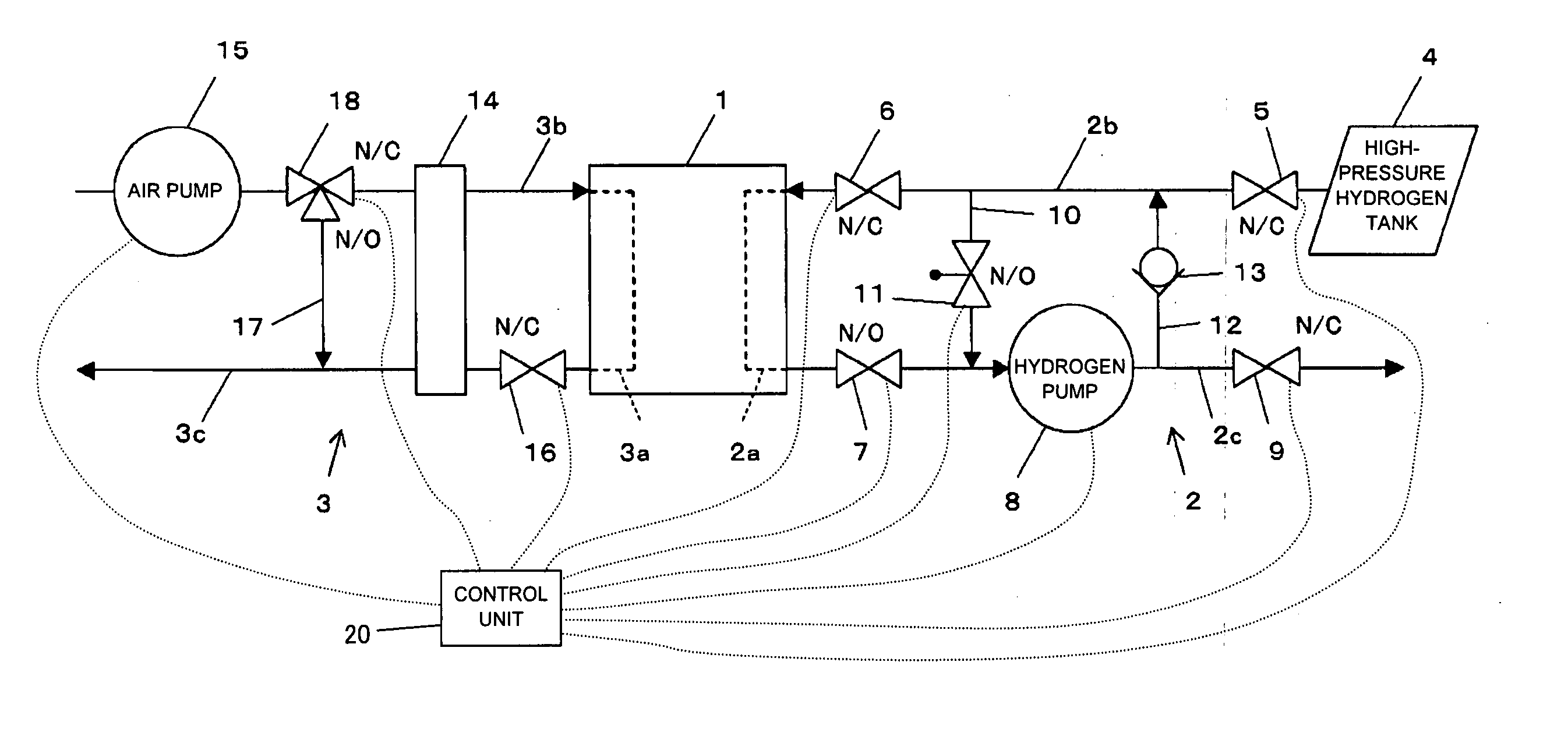
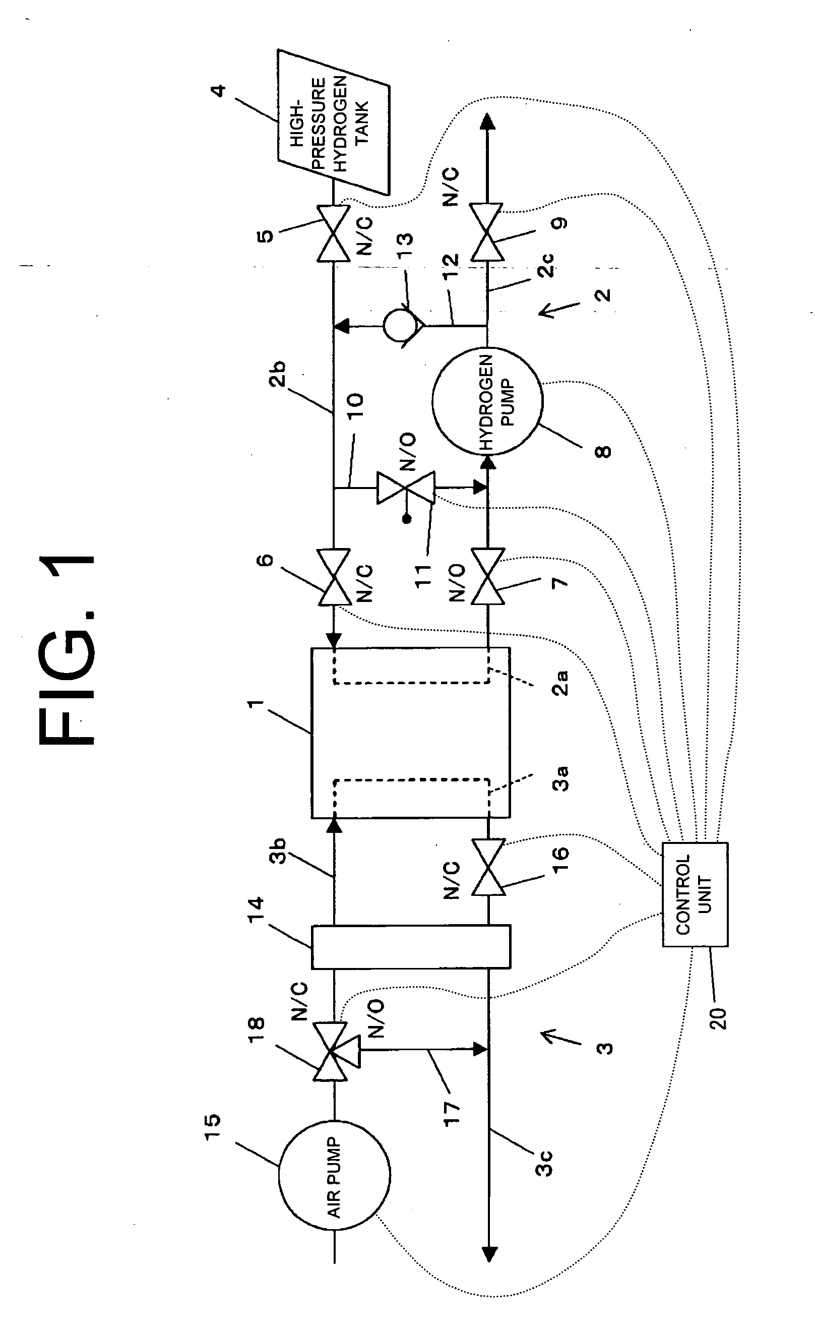
[0016]FIG. 1 shows a schematic view of the fuel cell system according to the first preferred embodiment of the present invention. It is noted that the reference marks “N / O”, “N / C” respectively denote “normal open” and “normal close”. The fuel cell system includes a stack 1 of a fuel cell (hereinafter referred to a FC stack 1) in which electricity is generated through electrochemical reaction of hydrogen and atmospheric oxygen, and is capable of using electric power which is generated by the FC stack 1 as a drive source of a vehicle. Also, the fuel cell system includes a hydrogen flowing passage 2 for allowing hydrogen to be supplied to a hydrogen electrode of the FC stack 1 and an air flowing passage 3 for allowing air (or oxygen) to be supplied to an oxygen electrode of the FC stack 1.

[0017] The hydrogen flowing passage 2 includes a passage 2...


PUM


Abstract

A fuel cell system includes a fuel cell stack, a hydrogen flowing passage, an air flowing passage and a control valve. At least one of the gas flowing passages includes a bypass, a selecting means, a gas flowing means and a control unit. The bypass allows a gas to flow therethrough so as to detour the fuel cell stack and the control valve. The selecting means selects one of a passage which passes through the fuel cell stack and the bypass. The gas flowing means flows the gas to the bypass. In the control unit, the through passage is selected by the selecting means when the system is operated, The bypass is selected by the selecting means when the operation of the system is stopped. The gas is flowed to the bypass by operating the gas flowing means when the control valve is frozen thereby heating the control valve.

Description

BACKGROUND OF THE INVENTION [0001] The present invention relates to a fuel cell system and, in particular, to a fuel cell system which generates electricity by supplying hydrogen and air to a fuel cell stack respectively through a hydrogen flowing passage and an air flowing passage. [0002] In recent years, a fuel cell system, which generates electricity through electrochemical reaction of hydrogen and oxygen, has been attracted as an energy source. If an outdoor air temperature drops to below zero in such a fuel cell system, moisture in a gas exhausted from a stack of a fuel cell condenses and freezes on a control valve such as an exhaust valve or a check valve which is located on the gas flowing passage, or a moisture remaining in the gas flowing passage freezes on the control valve, thereby preventing the control valve from openirig and closing. In this case, the system is not started until a freeze of the control valve is dissolved, and a relatively long time is needed until the ...

Claims


Application Information

Patent Timeline
IPC IPC(8): H01M8/02H01M8/04H01M8/18H01M8/24
CPCB60L11/1885B60L11/1894B60L11/1898Y02T90/34H01M8/04089H01M8/04223Y02E60/50B60L2240/36B60L50/72B60L58/31B60L58/34Y02T90/40H01M8/043H01M8/04225
Inventor HIRANO, TAKAYUKIYAMADA, KAZUHOKAGAMI, MASANAOFUJII, TOSHIROHOSHINO, TATSUYUKISHIROMARU, KATSUTOSHI
Owner TOYOTA IND CORP
Why Eureka
Try Eureka