
Dynamically tuned antenna used for multiple purposes

a dynamically tuned, antenna technology, applied in the direction of polarisation/directional diversity, resonant antennas, wireless communication, etc., can solve the problems of affecting pushed the existing analog technology to a capacity limit or ceiling, and large space occupation, so as to facilitate the reception of gps signals, avoid the cost of complete re-design of mobile communication devices, and reduce the cost of mobile communication devices.

Inactive Publication Date: 2005-05-26
NOKIA CORP
View PDF21 Cites 5 Cited by
  • Summary
  • Abstract
  • Description
  • Claims
  • Application Information

AI Technical Summary

Benefits of technology

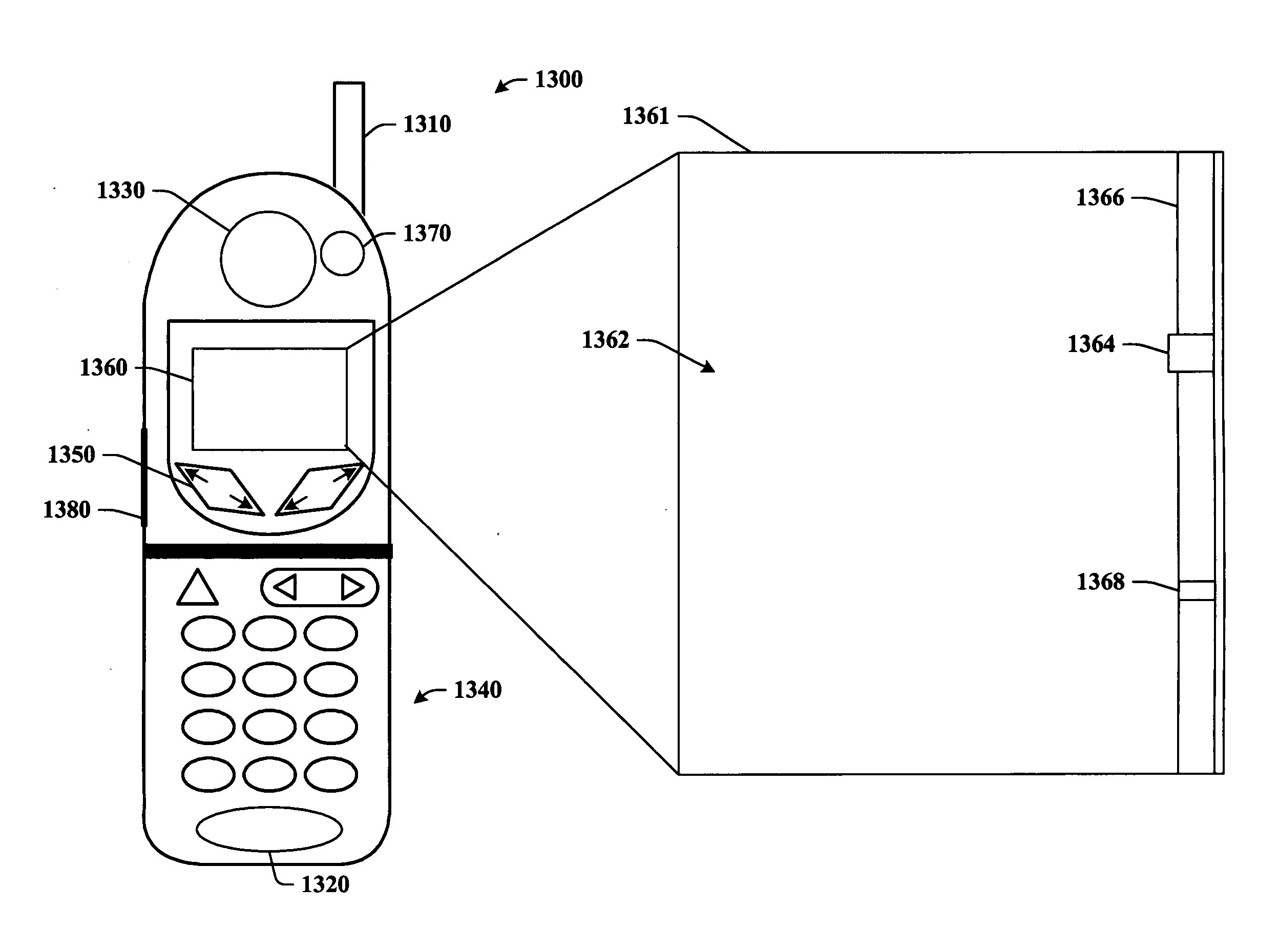
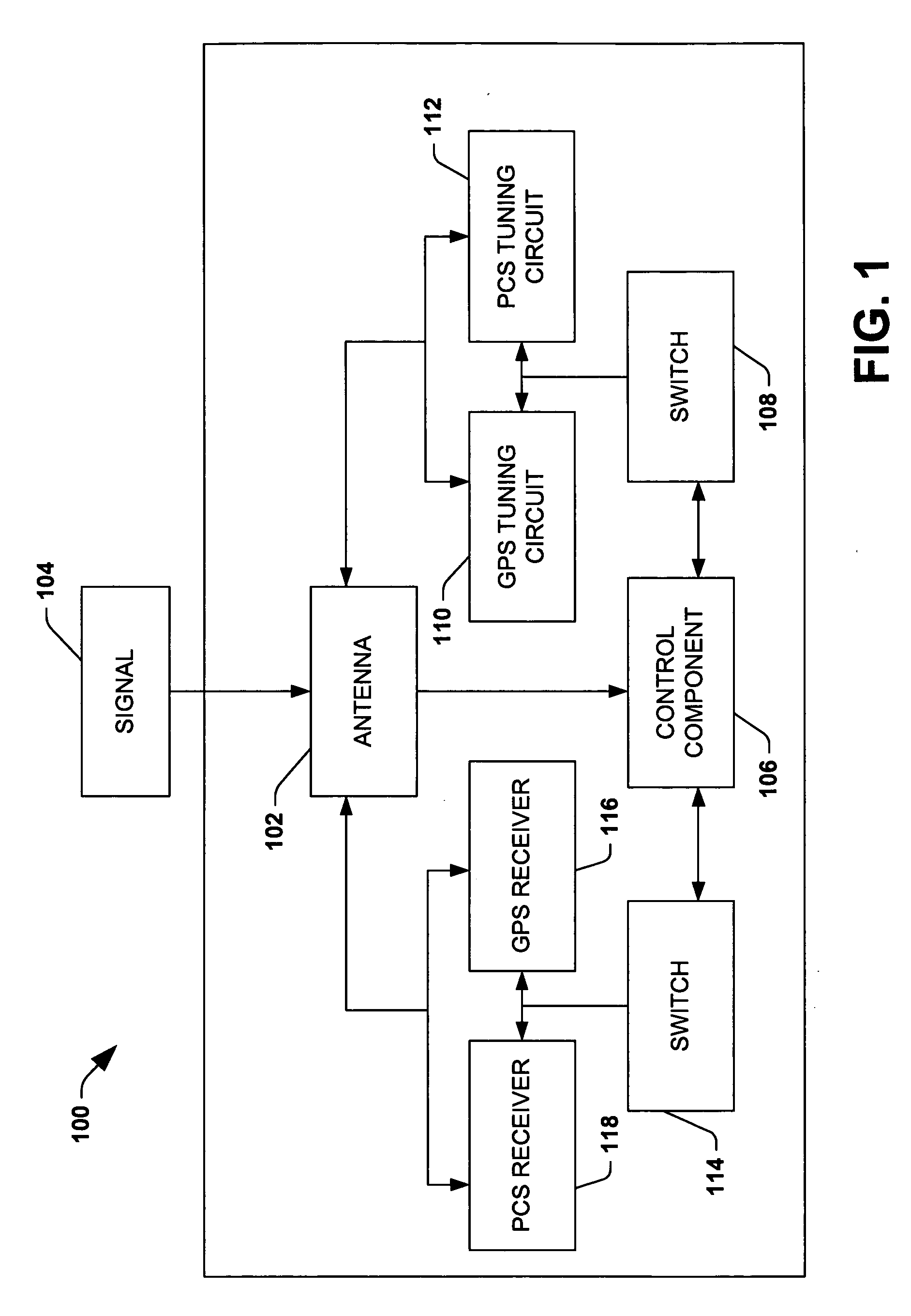
[0012] The present invention enables utilization of pre-existing designs within mobile communication devices (e.g., portable telephones) to provide receive diversity within such devices. Thus, substantial cost of complete re-design of mobile communication devices can be avoided while the communication devices are optimized for use with third generation wireless network protocols. Moreover, size, weight, and cost of mobile communication devices is not significantly affected when implemented with one or more aspects of the present invention. The present invention is a product of the inventor's realization that a substantial amount of designs of mobile communication devices comprise antennas that facilitate reception of GPS signals. Thus, through addition of tuning and reception circuitry, the antenna can be employed to receive GPS signals and PCS signals without requiring an additional antenna that is dedicated for receive diversity.
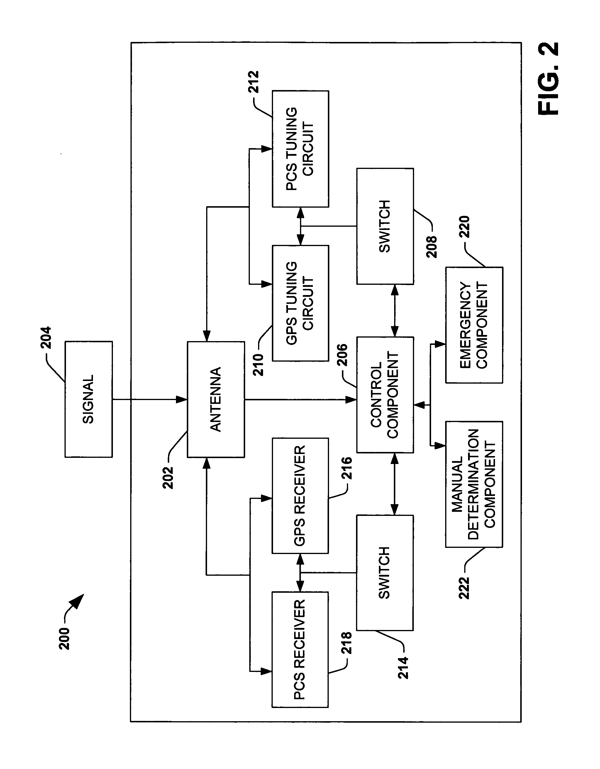
[0015] In accordance with another aspect of the present invention, a switch can be provided to selectably couple the second antenna to an appropriate tuning component. For instance, if the second antenna is configured to receive PCS signals and a GPS signal is desirably received by the second antenna, the switch can couple the second antenna to a tuning component that facilitates tuning the antenna to enable reception of GPS signals. Alternatively, in an instance that the second antenna is configured to receive GPS signals and a PCS signal is desirably receive by such antenna, the switch can couple the antenna to a tuning component that facilitates configuring the antenna for PCS signal reception. Similarly, components that effectuate processing, transduction, and / or manipulation of particular signals received by the antenna can be coupled to the antenna via a switch. For instance, a component designed to process and / or manipulate a GPS signal (e.g., a GPS receiver) can be automatically coupled to the second antenna via a switch upon a determination that receipt of a GPS signal is desirable. Additionally, a component designed to process and / or manipulate a PCS signal can automatically be coupled to the antenna via a switch upon a determination that receipt of a PCS signal is desirable.

Problems solved by technology

However, within a relatively short period of time, millions of new mobile communications subscribers, demanding more and more airtime, pushed the existing analog technology to a capacity limit or ceiling.
WCDMA and TD-SCDMA represent more complex enhancements that can entail more costly and complex components, new network designs, and longer verification and validation periods.
As antennas require a substantial amount of space within mobile communication devices, however, re-design of existing mobile communication devices may be required to provide necessary space for the additional antenna.
Such design can be costly and time-consuming, and the resulting design can require a mobile communication device to be larger and heavier than desirable by typical users.

Method used


Image

  • Dynamically tuned antenna used for multiple purposes
  • Dynamically tuned antenna used for multiple purposes
  • Dynamically tuned antenna used for multiple purposes

Examples


Embodiment Construction

[0031] The present invention is now described with reference to the drawings, wherein like reference numerals are used to refer to like elements throughout. In the following description, for purposes of explanation, numerous specific details are set forth in order to provide a thorough understanding of the present invention. It may be evident, however, that the present invention may be practiced without these specific details. In other instances, well-known structures and devices are shown in block diagram form in order to facilitate describing the present invention.

[0032] As used in this application, the terms “component,”“handler,”“model,”“system,” and the like are intended to refer to a computer-related entity, either hardware, a combination of hardware and software, software, or software in execution. For example, a component may be, but is not limited to being, a process running on a processor, a processor, an object, an executable, a thread of execution, a program, and / or a c...


PUM


Abstract

A system that effectuates receive diversity within a mobile communication device is provided. A first antenna facilitates reception of signals in a PCS band, and a second antenna facilitates reception of signals in a GPS band and a PCS band. Tuning of the second antenna depends upon a signal type relayed to the second antenna.

Description

TECHNICAL FIELD [0001] The present invention generally relates to mobile communications devices. More particularly, the present invention relates to utilizing a single antenna structure with respect to enabling receive diversity and GPS communications within a mobile communications device. BACKGROUND OF THE INVENTION [0002] Early mobile communication devices employed analog radio transmission such as Advanced Mobile Phone System (AMPS), for example. Such analog technologies were sufficient for an emerging mobile communications consumer market. However, within a relatively short period of time, millions of new mobile communications subscribers, demanding more and more airtime, pushed the existing analog technology to a capacity limit or ceiling. As a consequence, dropped calls and busy signals became common, which fueled a demand for an improved mobile communication network. [0003] In response to the demand, industry developed digital wireless technologies that could accommodate the ...

Claims


Application Information

Patent Timeline
IPC IPC(8): H01QH01Q1/24H01Q9/04H04B1/04H04B1/18H04B1/38H04B7/10H04B7/12H04M1/00
CPCH01Q1/243H01Q9/0442H04B1/0458H04B7/12H04B1/3805H04B7/10H04B1/18H01Q3/24H01Q1/24H01Q3/26
Inventor LI, KEVIN
Owner NOKIA CORP
Learn More