Actuator for shift-by-wire automatic transmission system

a technology of automatic transmission system and actuator, which is applied in the direction of braking system, coupling, gearing, etc., can solve the problems of relative slow and inaccurate shifting, and achieve the effects of low cost, high quality, and fast transmission speed

Active Publication Date: 2005-05-26
DUS OPERATING INC
View PDF7 Cites 7 Cited by
  • Summary
  • Abstract
  • Description
  • Claims
  • Application Information

AI Technical Summary

Benefits of technology

[0010] From the foregoing disclosure and the following more detailed description of various preferred embodiments it will be apparent to those skilled in the art that the present invention provides a significant advance in the technology of electric actuators for electronically controlled automatic transmissions. Particularly significant in this regard is the potential the invention affords for providing a high quality, reliable, relatively fast, accurate, and low cost assembly. Additional features and advantages of various preferred embodiments will be better understood in view of the detailed description provided below.

Problems solved by technology

This can result in relatively slow and inaccurate shifting.

Method used


Image

  • Actuator for shift-by-wire automatic transmission system
  • Actuator for shift-by-wire automatic transmission system
  • Actuator for shift-by-wire automatic transmission system

Examples


first embodiment

[0034]FIG. 7 shows an electric actuator 90 according to an alternative embodiment of the present invention wherein common reference numbers are utilized to indicate common structure. The electric actuator 90 is substantially the same as the electric actuator 14 of the first embodiment except that a pull-type electric solenoid 92 is used rather than the push-type electric solenoid 72. This electric actuator 90 demonstrates that the various components such as the release mechanism 56 can take many forms within the scope of the present invention.
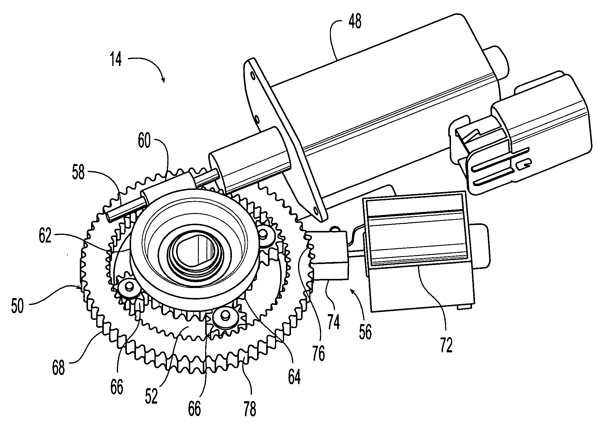
second embodiment

[0035] The illustrated release mechanism 56 of the second embodiment includes the pull-type electric linear solenoid 92 and a locking member or pawl 94 operatively connected to and moved by the solenoid 92. The illustrated locking pawl 94 is provided with the row of teeth 76 that are sized and shaped to cooperate with the external locking teeth 78 outwardly projecting from an outer periphery of the ring gear 68. The locking pawl 94 is pivoted about a pivot 96 by the solenoid 92 toward and away from the ring gear 68 between an unlocking position and a locking position. In the unlocking position, the teeth 76 are spaced apart from and disengaged from the locking teeth 78 of the ring gear 68 so that the ring gear 68 is free to rotate. In the locking position, the teeth 76 are engaged with the locking teeth 78 of the ring gear 68 to prevent the ring gear 68 from rotating.

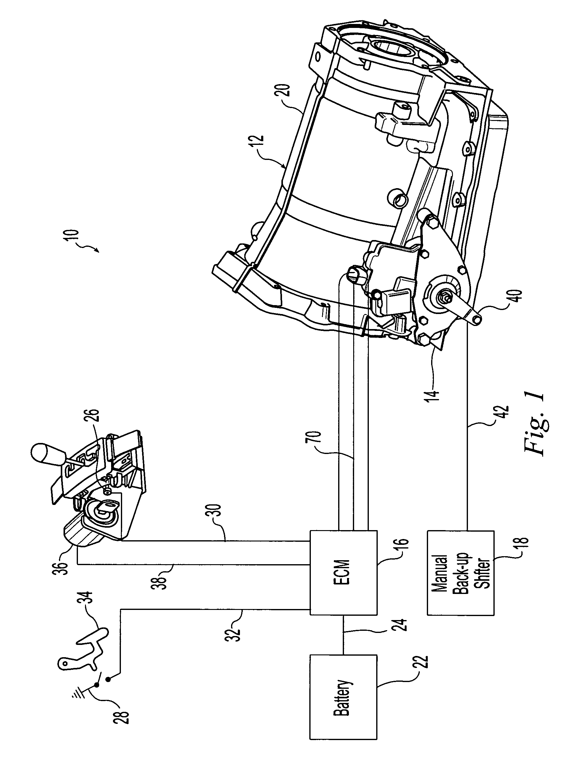
[0036] The solenoid 92 is electrically connected to the ECM 16 in a suitable manner such as, for example by wires or ...


PUM


Abstract

An electric actuator for an automatic transmission includes an adapter to transmit rotary motion between the adapter and the transmission. An electric motor has an output shaft operably connected the adapter by a gear set which includes a ring gear. A release mechanism includes a solenoid which selectively moves a lock member. In a first position, the lock member engages the ring gear to lock the ring gear so that the adapter is rotated by rotary motion of the output shaft and the adapter rotates to a predetermined zone about a desired gear position. In a second position, the lock member is out of engagement with the ring gear to permit rotation of the ring gear so that the adapter is rotated by internal forces of the transmission and the adapter automatically self-aligns to the exact desired gear position when the adapter is within the predetermined zone.

Description

CROSS-REFERENCE TO RELATED APPLICATIONS [0001] This application claims the benefit of provisional patent application No. 60 / 525,026 filed on Nov. 25, 2003, the disclosure of which is expressly incorporated herein in its entirety by reference.STATEMENT REGARDING FEDERALLY SPONSORED RESEARCH [0002] Not Applicable REFERENCE TO MICROFICHE APPENDIX [0003] Not Applicable FIELD OF THE INVENTION [0004] The present invention generally relates to an electronically controlled automatic transmission system for motor vehicles, and more particularly, an improved electric actuator for such an automatic transmission system. BACKGROUND OF THE INVENTION [0005] An electronically controlled transmission system is commonly referred to as a “shift-by-wire” transmission system. In some shift-by-wire automatic transmission systems, an input shaft outwardly projects from a transmission gear housing and is rotated to shift gears in the transmission. The transmission input shaft is rotated by an electric actu...

Claims


Application Information

Patent Timeline
Patent Type & Authority Applications(United States)
IPC IPC(8): B60B27/00F16D1/06F16H1/36F16H1/16F16H3/44F16H61/02F16H61/22F16H61/28F16H61/32F16H63/38H02K7/116
CPCF16H61/22F16H2061/326F16H61/32
Inventor WANG, YONG QIANG
Owner DUS OPERATING INC
Why Eureka
Try Eureka