Occlusion device for asymmetrical uterine artery anatomy

a uterine artery and asymmetric technology, applied in the field of occlusion devices for asymmetrical uterine arteries, can solve the problems of difficult use, known risks and disadvantages, and drastic treatment of hysterectomy, and achieve the effect of simple and convenient use and effective therapeutic treatmen

Inactive Publication Date: 2005-05-26
VASCULAR CONTROL SYST
View PDF99 Cites 33 Cited by
  • Summary
  • Abstract
  • Description
  • Claims
  • Application Information

AI Technical Summary

Benefits of technology

[0021] The invention allows for the non-surgical location and occlusion of blood vessels such as the uterine artery, providing effective therapeutic treatment. Importantly, the present invention allows for the occlusion of a female patient's uterine artery without the need for radiographic equipment or for extensive training in the use of radiographic techniques. The devices and methods are simple and readily used for treating uterine fibroids, dysfunctional uterine bleeding (DUB), adenomyosis, post-partum hemorrhage, and other uterine disorders. The devices, systems and methods embodying features of the invention allow for the occlusion of both uterine arteries in those situations in which the uterine anatomy is not symmetrical.

Problems solved by technology

However, hysterectomy is a drastic treatment, having many undesirable characteristics.
While Bateman reported some success, this procedure involves opening the abdominal cavity, with the known attendant risks and disadvantages.
The devices and methods described in Burbank '601 have been useful in occluding a uterine artery, however there have been some difficulties encountered with their use.
However, many physicians do not possess the training or equipment necessary to perform catheter-based uterine artery embolization under radiologic direction.
While these procedures have shown much promise, they are not always successful with many female patients who have asymmetrical uterine artery anatomy.

Method used


Image

  • Occlusion device for asymmetrical uterine artery anatomy
  • Occlusion device for asymmetrical uterine artery anatomy
  • Occlusion device for asymmetrical uterine artery anatomy

Examples


Embodiment Construction

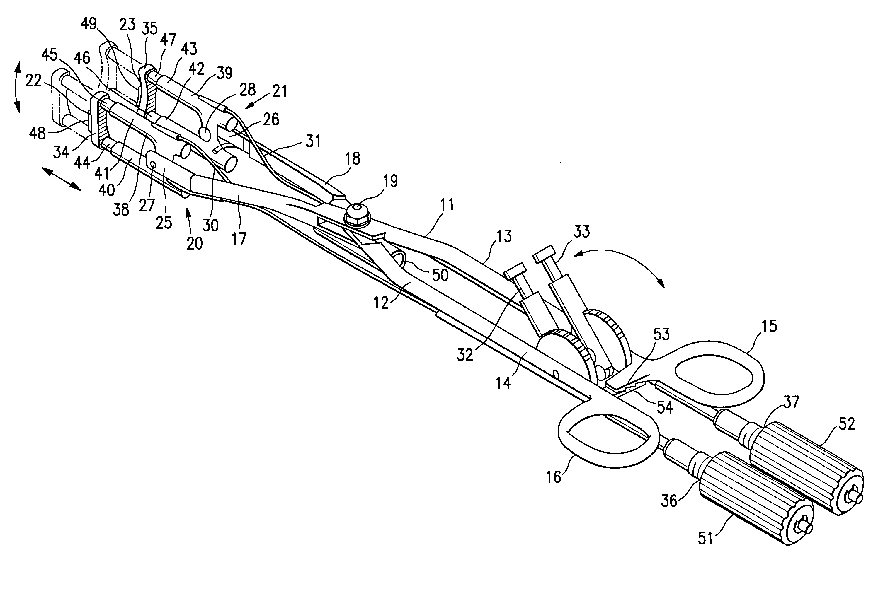
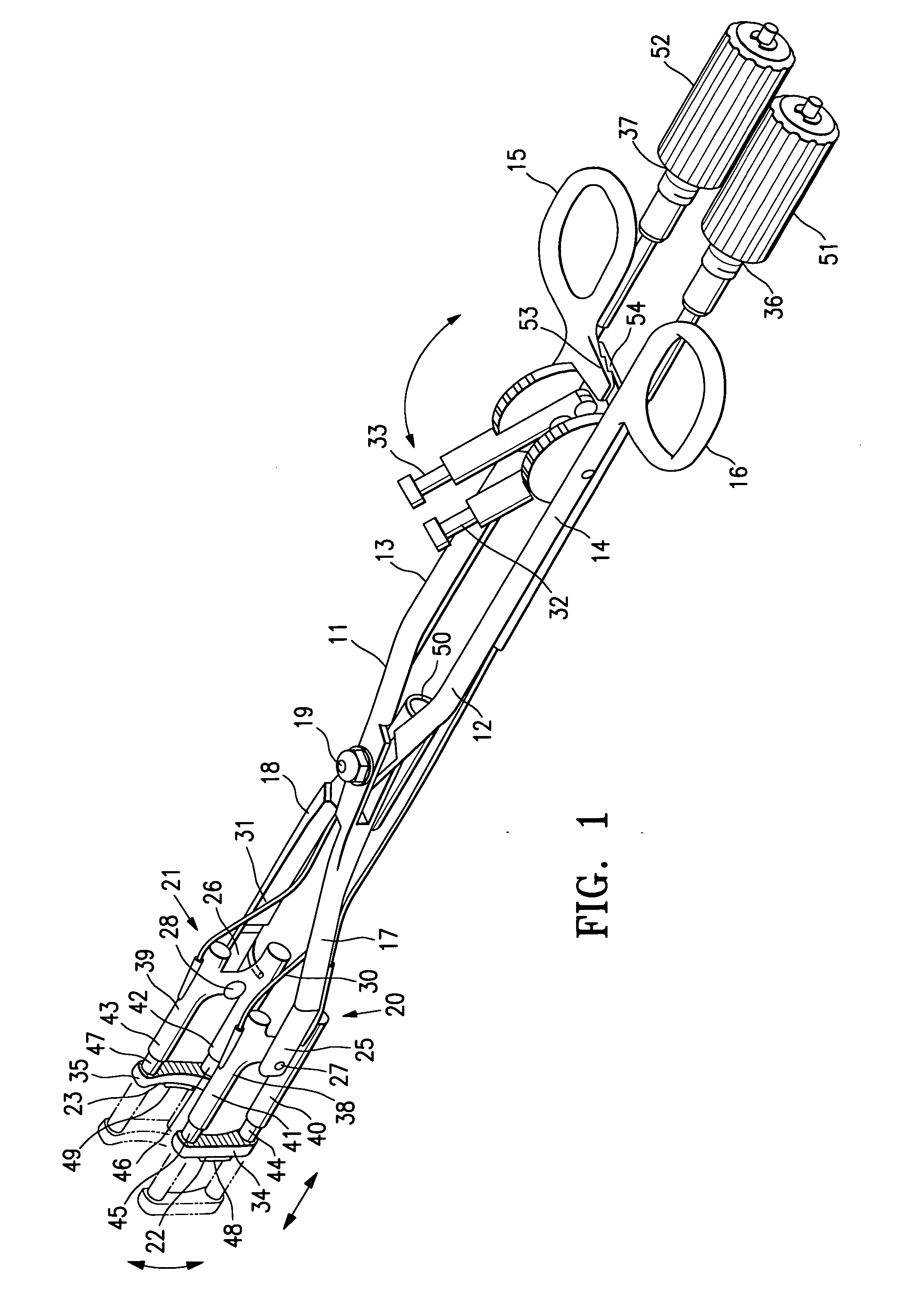
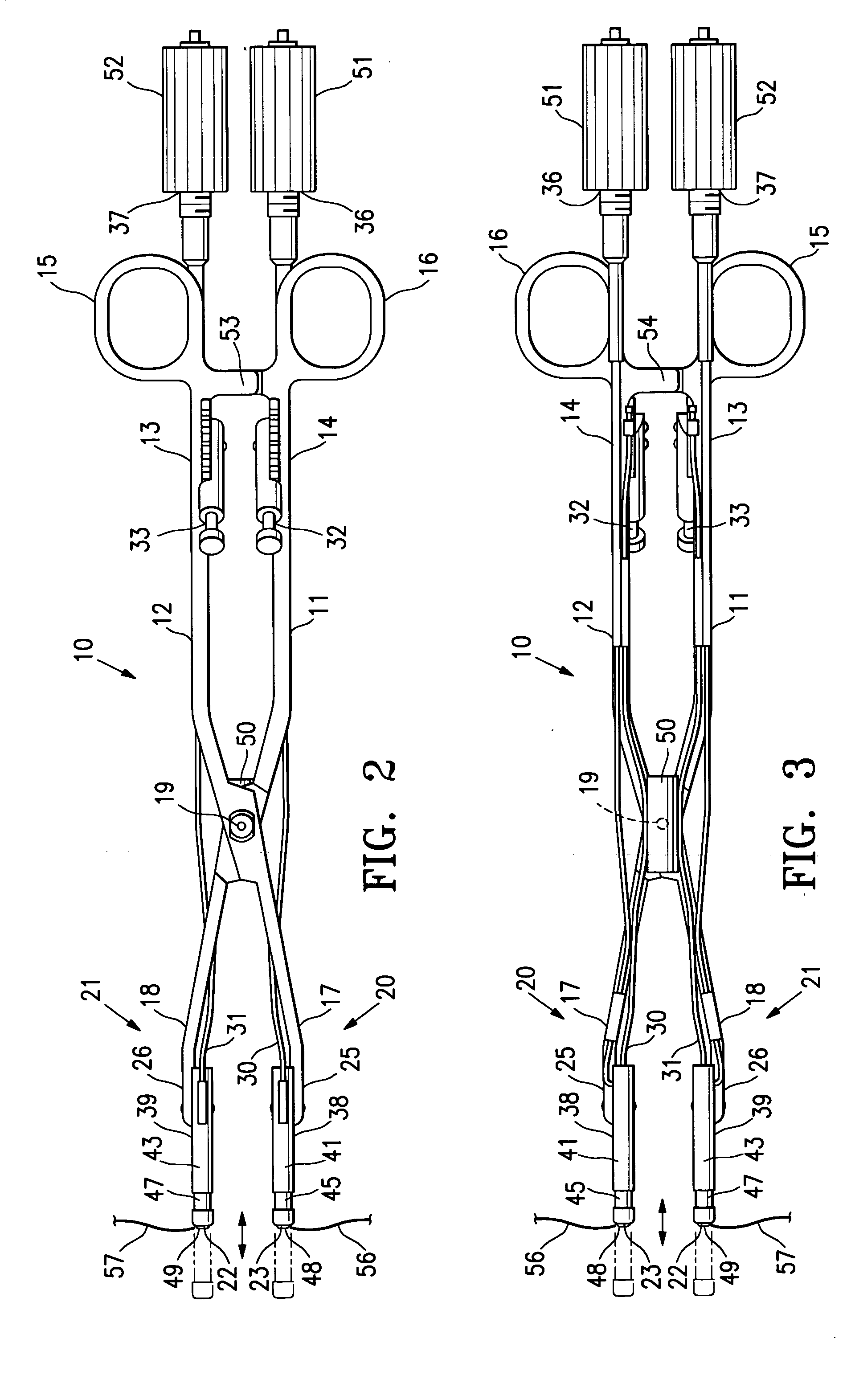
[0034]FIGS. 1-6 illustrate a relatively non-invasive intra-vaginal occluding device 10 embodying features of the invention. The device 10 includes a pair of elongated occluding members 11 and 12, each of which has a proximal shaft section 13 and 14 respectively with finger grips 15 and 16, and distal shaft sections 17 and 18 with occluding elements 20 and 21 having pressure-applying surfaces 22 and 23 respectively. The elongated occluding members 11 and 12 are pivotally connected at pivot point 26.

[0035] The occluding elements 20 and 21 on the distal portion of the distal shaft sections 17 and 18 are shown pivotally mounted to the distal ends 25 and 26 of the distal shaft sections 17 and 18 respectively at pivots 27 and 28. The occluding elements 20 and 21 are rotated about the pivotal connections 27 and 28 by control cables 32 and 33 which are connected to control arms 30 and 31 respectively mounted on the proximal shaft sections 13 and 14. The control arms 32 and 33 are provided ...


PUM


Abstract

An occluding device is disclosed for occluding a female patient's uterine arteries which have unsymmetrical anatomy with respect to the patient's uterine cervix. The occluding device has a pair of pivotally connected occluding members, with at least one of the occluding member having a movable occluding element on a distal shaft section of the occluding member. The position and orientation of the occluding elements on the distal shaft sections may be adjusted by operative members on the proximal shaft sections of the occluding members to accommodate for asymmetrical uterine artery anatomy. The occluding elements have pressure applying surfaces with one or more blood flow sensors such as Doppler chips which help the physician to better identify the uterine artery and to monitor blood flow therein. A tenaculum-like guiding element configured to be secured within the patient's uterine cervix, may be provided to guide the occluding device to the patient's cervix.

Description

FIELD OF THE INVENTION [0001] The invention is generally directed to the treatment of uterine disorders by detecting and regulating blood flow through one or both of the patient's uterine arteries. BACKGROUND OF THE INVENTION [0002] Hysterectomy (surgical removal of the uterus) is performed on approximately 600,000 women annually in the United States. Hysterectomy is often the therapeutic choice for the treatment of uterine cancer, adenomyosis, menorrhagia, prolapse, dysfunctional uterine bleeding (abnormal menstrual bleeding that has no discrete anatomic explanation such as a tumor or growth), and muscular tumors of the uterus, known as leimyoma or uterine fibroids. [0003] However, hysterectomy is a drastic treatment, having many undesirable characteristics. Thus, any method which can approximate the therapeutic result of a hysterectomy without removing the uterus would be a significant improvement in this field. Newer treatment methods have been developed for some diseases which m...

Claims


Application Information

Patent Timeline
Patent Type & Authority Applications(United States)
IPC IPC(8): A61B17/12A61B17/28A61B17/42
CPCA61B17/12A61B17/42A61B2017/4225A61B2017/2944A61B2017/4216A61B2017/2927
Inventor BURBANK, FRED H.ALTIERI, GREIG E.JONES, MICHAEL L.OLSON, ED
Owner VASCULAR CONTROL SYST
Why Eureka
Try Eureka