Spinal stabilization systems

a technology of spinal column and stabilizing element, which is applied in the field of spinal column stabilization devices, can solve the problems of significant load placed on the stabilizing assembly, pain and complications, loosening of the assembly from the vertebrae, breaking of the assembly, etc., and achieves the effects of preserving or simulating flexion, extension, compression and rotation of the spine, and lateral bending

Active Publication Date: 2005-05-26
ST CLOUD CAPITAL PARTNERS III SBIC LP
View PDF41 Cites 698 Cited by
  • Summary
  • Abstract
  • Description
  • Claims
  • Application Information

AI Technical Summary

Benefits of technology

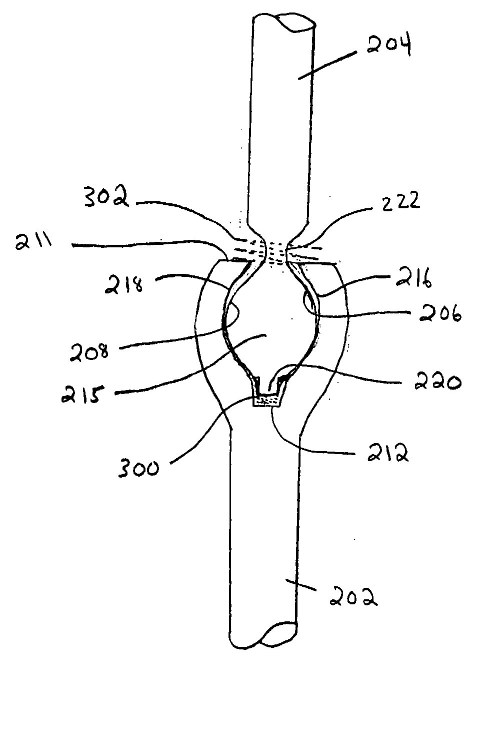
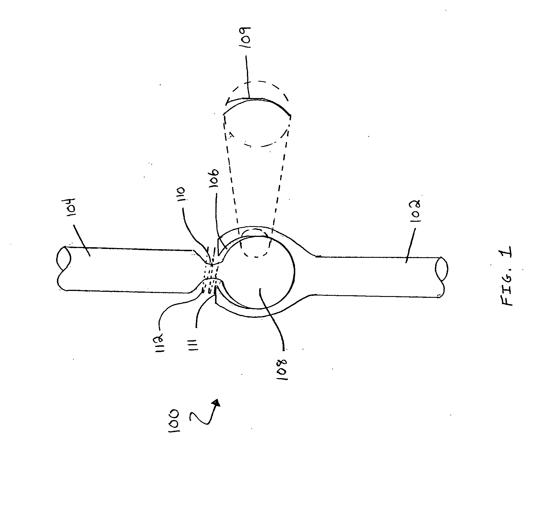
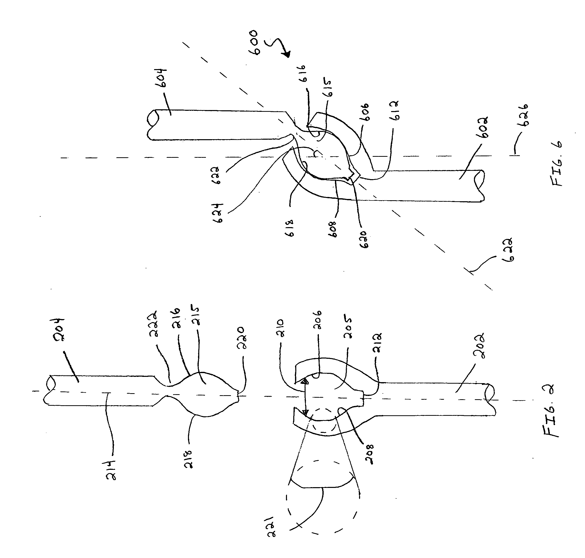
[0008] Spinal stabilizing elements and spinal stabilization systems are provided herein. The stabilization systems combine at least one disc prosthesis and/or at least one disc nucleus replacement with one or more stabilizing elements to retain or simulate at least some of the physiological intervertebral mobility of the spine by distributing the stress and mobility functions between the disc prosthesis or disc nucleus replacement and the stabilizing elements. Specifi

Problems solved by technology

In some instances, the pain and complications caused by these conditions may be bad enough to require that one or more vertebra, facet joints, and/or intervertebral discs be removed from the spinal column.
One drawback of rigid fixation derives from the fact that significant loads are placed on the stabilizing assemblies and particularly on the anchoring sites thereof.
These loads may result in the loosening of the assembly from the vertebra or even the breaking of the assembly

Method used


Image

  • Spinal stabilization systems
  • Spinal stabilization systems
  • Spinal stabilization systems

Examples


first embodiment

[0076] In a first embodiment, in accordance with this aspect of the invention, the dynamic stabilizing element is the dynamic spinal orthosis disclosed in U.S. Pat. No. 5,672,175, the disclosure of which is incorporated herein by reference. FIGS. 17 and 18 illustrate a spinal stabilization system that used two spinal stabilizing elements similar to those disclosed in the '174 patent. Here, the spinal stabilization system includes two dynamic stabilizing elements, each composed of a flexible rod 1702, 1704. The flexible rods are each attached to one vertebra in a manner that allows the rod to translate longitudinally with respect to that vertebra, where a “longitudinal” translation refers to a translation along the long axis of the spine. The flexible rods are also each attached to another vertebra in a manner that does not allow the rod to translate longitudinally with respect to that vertebra. In the embodiment depicted in FIG. 17, each rod is attached by a first connector 1706, 17...

second embodiment

[0077] In a second embodiment, in accordance with this aspect of the invention, the spinal stabilization system includes two dynamic stabilizing elements, wherein each dynamic stabilizing element is composed of a damping element and each damping element is a dynamic bias device as disclosed in U.S. Pat. No. 6,402,750, the disclosure of which is incorporated herein by reference. In this embodiment of the invention, the two stabilizing elements are disposed in a spaced-apart, substantially parallel relation, typically at the posterior of the spine, on opposite sides of the spinous processes. As described in the '750 patent, the damping elements may be springs, including coiled springs, leaf springs, articulated leaf springs, torsional springs, torsional leaf springs, or articulated torsional leaf springs. Each damping device is connected across a first and a second vertebra by a first and a second connector, respectively. Suitable connectors include screws, hooks and the like. FIG. 19...


PUM


Abstract

Spinal stabilizing elements and spinal stabilization systems composed of spinal stabilizing elements in combination with disc prostheses or disc nucleus replacements are provided. The stabilizing elements and stabilization systems are designed to preserve the natural mobility of vertebral discs and facet joints in patients with facet joint disease or patients who has undergone a prior destabilizing procedure, such as a facetectomy. The stabilizing elements may be pivoting elements or dynamic elements.

Description

FIELD OF THE INVENTION [0001] The present invention provides devices for the stabilization of the spinal column. In particular, the present invention provides spinal stabilizing elements and spinal stabilization systems that combine an intervertebral disc prosthesis with a variety of trans-vertebral stabilizing elements to retain, at least in part, the natural physiological degrees of motion of the spine. BACKGROUND OF THE INVENTION [0002] Degenerative disc disease, spinal trauma and tumors are common and painful conditions suffered by a significant portion of the population. In some instances, the pain and complications caused by these conditions may be bad enough to require that one or more vertebra, facet joints, and / or intervertebral discs be removed from the spinal column. In these instances, arthrodesis or bone fusion are common treatments used to facilitate the realignment and / or fixation of the spinal elements. Typically, two types of assemblies are known for securing one or...

Claims


Application Information

Patent Timeline
IPC IPC(8): A61B17/70A61F2/30A61F2/44
CPCA61B17/7007A61B17/7008A61B17/701A61B17/7011A61B17/7023A61B17/7032A61F2002/443A61B17/7049A61F2/4425A61F2002/30563A61F2002/30568A61F2002/30662A61F2002/30663A61B17/7037
Inventor MALEK, MICHEL H.
Owner ST CLOUD CAPITAL PARTNERS III SBIC LP
Why Eureka
Try Eureka