Liquefied natural gas structure

a technology of liquefied natural gas and structure, which is applied in the direction of liquid handling, packaging goods, container discharging methods, etc., can solve the problems of less desirable on-shore facilities for residents who live near facilities, and achieve the effects of reducing the amount of sea life and debris, reducing and minimizing the effect of standing waves

Inactive Publication Date: 2005-06-02
SHELL OIL CO
View PDF33 Cites 91 Cited by
  • Summary
  • Abstract
  • Description
  • Claims
  • Application Information

AI Technical Summary

Benefits of technology

[0010] In one embodiment, docking equipment may be disposed on an upper surface of the body. The docking equipment may be configured to couple an LNG carrier to the body. By placing the docking equipment directly on the body, instead of using, for example, separate mooring platforms, the LNG carrier may be coupled closer to the body. Coupling an LNG carrier close to the body may facilitate transfer of LNG from the LNG carrier to the LNG storage tanks. Additionally, the body may also provide some protection from waves while the LNG carrier is docked alongside the body.
[0020] LNG structures may be constructed on-shore. After an LNG structure has been constructed, the structure may be towed to an appropriate site and positioned on the bottom of a body of water. The process of building on-shore involves excavating a hole for construction of the LNG structure. After the structure is completed, the structure may be towed to an offshore site. To ensure that the structure may be towed through relatively shallow harbors and channels, a number of features may be incorporated into the LNG structure to reduce the weight of the structure. In certain embodiments, at least a portion of the structure may be composed of a structural-grade lightweight concrete. In an embodiment, a series of projections may be built extending from the bottom of the structure. The projections may be arranged such that one or more compartments are formed on the bottom of the body. During floatation of the structure, at least a portion of the compartments may temporarily trap air between the body and the water. Trapping air underneath the structure may improve the buoyancy of the structure. A combination of structural-grade lightweight concrete and air compartments may also be used to improve the buoyancy of the structure.

Problems solved by technology

The inherent dangers of handling LNG make such on-shore facilities less desirable to inhabitants who live near the facilities.

Method used


Image

  • Liquefied natural gas structure
  • Liquefied natural gas structure
  • Liquefied natural gas structure

Examples


Embodiment Construction

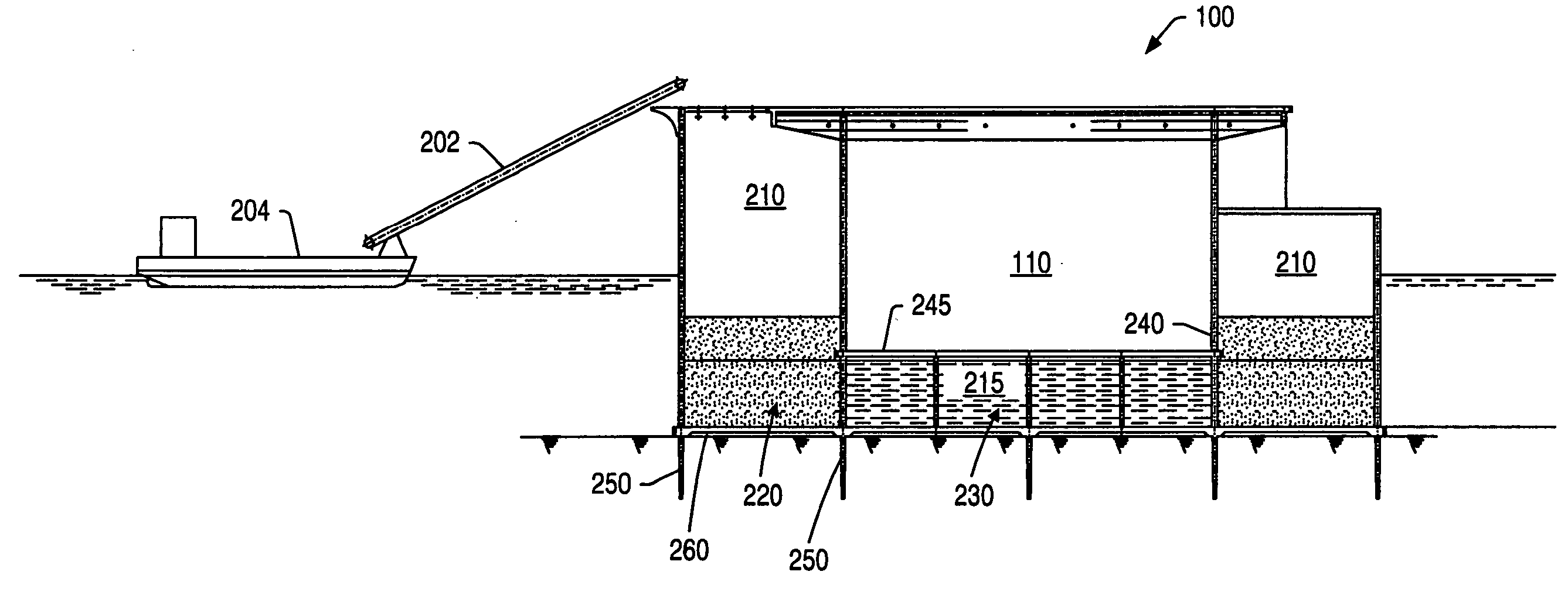
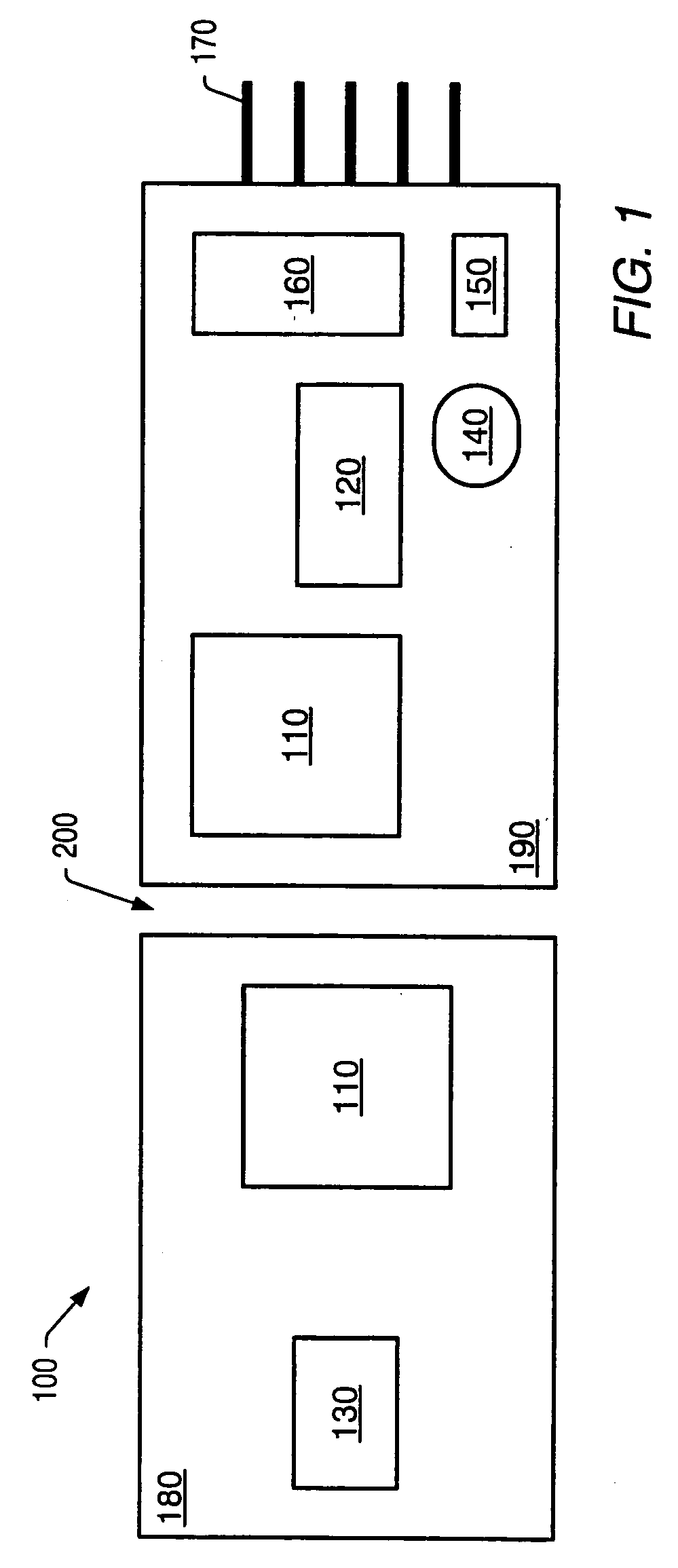
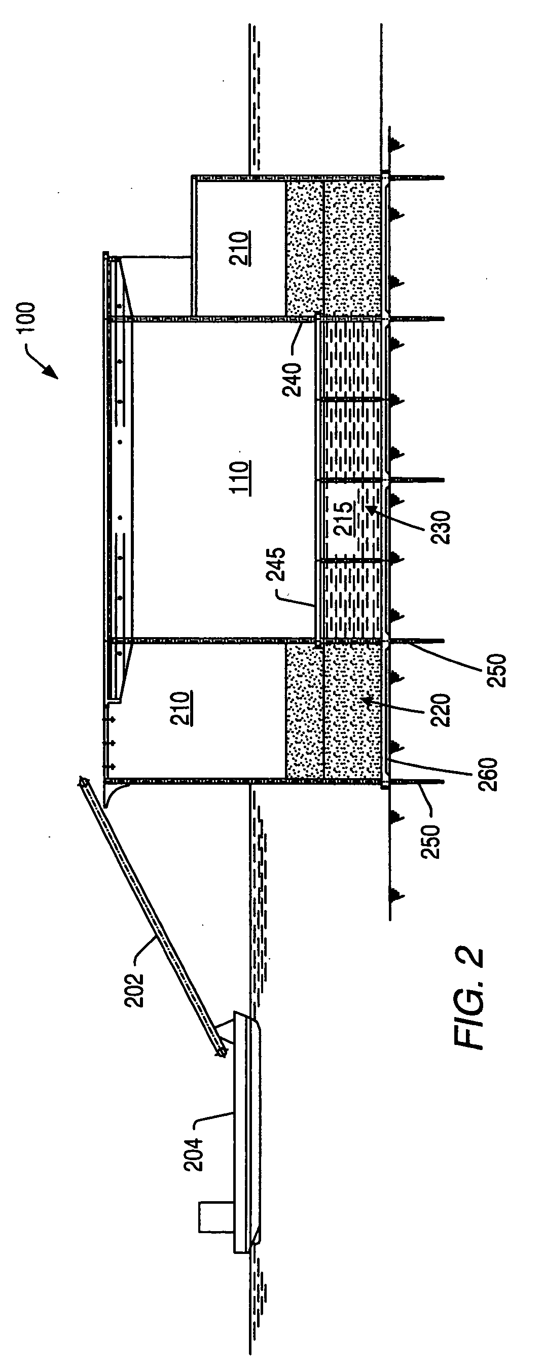
[0048] An offshore liquefied natural gas (“LNG”) receiving and storage structure may allow LNG carriers to berth directly alongside the structure and unload LNG. The LNG structure may include one or more tanks capable of storing LNG. The LNG structure may transfer LNG from the tanks to an LNG vaporization plant disposed on the structure. The vaporized LNG may then be distributed among commercially available pipelines.

[0049]FIG. 1 depicts an embodiment of an LNG structure. An LNG structure 100 may have a layout that includes LNG tanks 110 on the structure with vaporization process equipment 120 and utilities, docking equipment, living quarters 130, flares 140, vents 150, metering equipment 160, and pipelines 170 for exporting natural gas. The living quarters 130, vaporization plant 120, and / or other process equipment may be positioned on an upper surface of the structure 100, such as on an upper surface of unit 180 and / or unit 190. The layout may be designed according to Fire / Explos...


PUM

PropertyMeasurementUnit
temperatureaaaaaaaaaa
angleaaaaaaaaaa
distanceaaaaaaaaaa

Abstract

An offshore liquefied natural gas structure may receive, store, and process liquefied natural gas from carriers. A structure may be a gravity base structure. A structure may include a system of ballast storage areas, transfer equipment to offload liquefied natural gas from a carrier, docking equipment to allow direct mooring with carriers, platforms to elevate equipment, water intake systems to provide water to the structure, wave deflectors, and / or projections extending from a bottom of the structure. A portion of the structure may be composed of lightweight concrete. Pipelines may be coupled to the structure to export processed natural gas onshore. Living quarters, flare towers, and export line metering equipment may be included on the structure.

Description

CROSS-REFERENCE TO RELATED APPLICATIONS [0001] This application claims the benefit of U.S. Provisional Application No. 60 / 515,541, filed Oct. 29, 2003 which is incorporated herein by reference.BACKGROUND OF THE INVENTION [0002] 1. Field of Invention [0003] The invention generally relates to structures configured to store liquefied natural gas and distribute natural gas. More specifically the invention relates to liquefied natural gas processing. [0004] 2. Description of Related Art [0005] Natural gas is becoming a fuel of choice for power generation in the U.S. and other countries. Natural gas is an efficient fuel source that produces lower pollutant emissions than many other fuel sources. Additionally, gains in efficiency of power generation using natural gas and the relatively low initial investment costs of building natural gas based power generation facilities, make natural gas an attractive alternative to other fuels. [0006] Distribution and storage of an adequate supply of nat...

Claims


Application Information

Patent Timeline
Patent Type & Authority Applications(United States)
IPC IPC(8): B65B1/20B65B1/28B65B3/18B65B3/22F17C1/00F17C3/00F17C6/00F17C9/00F17C9/02
CPCF17C1/002F17C3/005F17C6/00F17C9/00F17C2201/0104F17C2201/0119F17C2201/0128F17C2201/0147F17C2201/0157F17C2201/0195F17C2201/032F17C2201/052F17C2203/012F17C2203/0333F17C2203/035F17C2203/0354F17C2203/0358F17C2203/0604F17C2203/0607F17C2203/0624F17C2203/0629F17C2203/0631F17C2203/0639F17C2203/0643F17C2203/0646F17C2203/0648F17C2203/0673F17C2203/0678F17C2205/013F17C2205/0323F17C2205/0332F17C2205/0338F17C2205/037F17C2209/221F17C2209/225F17C2209/227F17C2209/228F17C2209/232F17C2221/033F17C2223/0161F17C2223/033F17C2225/0123F17C2225/035F17C2227/0135F17C2227/0157F17C2227/0178F17C2227/0185F17C2227/0304F17C2227/0318F17C2227/0327F17C2227/0383F17C2227/0393F17C2227/0395F17C2227/0397F17C2250/036F17C2250/0404F17C2250/0408F17C2250/043F17C2250/0439F17C2250/0443F17C2250/0491F17C2250/061F17C2250/0626F17C2250/0631F17C2260/012F17C2260/021F17C2260/022F17C2260/036F17C2260/053F17C2265/022F17C2265/031F17C2265/033F17C2265/034F17C2265/037F17C2265/04F17C2265/05F17C2265/068F17C2265/07F17C2270/0105F17C2270/0121
Inventor KOEHLER, GREGORY JOHNMORRISON, DENBY GREYWALTERS, KEITH BELLMEEK, HARKE JANWILHELMUS VAN WEERT, PAUL JOHANNES GERARDUSBOWRING, STEVEN JAMESFIGGERS, ROBERT FORRESTBOWEN, KELLY GEORGEKIM, WANJUNTHOMSON, DAVID ALEXANDER
Owner SHELL OIL CO
Why Eureka
Try Eureka