Vacuum lamination device and vacuum lamination method

Inactive Publication Date: 2005-06-02
FUJI ELECTRIC HLDG CO LTD
View PDF4 Cites 18 Cited by
  • Summary
  • Abstract
  • Description
  • Claims
  • Application Information

AI Technical Summary

Benefits of technology

[0015] With the structure described above, the processing space is hermetically sealed by the cover member. Air in the processing space is evacuated through the discharge port formed in the frame member. The uneven portion of the base plate forms an evacuation layer upon degassing the lamination member, thereby facilitating the evacuation of the lamination member.
[0016] In the present invention, the uneven portion is formed on the surface of the base plate contacting the lamination member. Accordingly, it is possible to ensure the evacuation layer between the lamination member and the base plate without providing a specific evacuation layer member, thereby degassing the lamination member with the simple structure and reducing manufacturing cost of the vacuum lamination device. Further, it is possible to eliminate an evacuation layer member having

Problems solved by technology

A large amount of fossil fuel has been consumed since Industrial Revolution, and the global environment has been worsened due to air pollution and global warming by CO2.
Particularly, when a large solar cell module such as the amorphous silicon solar cell is produced, due to the insufficient evacuation, it is difficult to eliminate bubbles between the laminated members constituting the solar cell module.
Accordingly, the layer structure becomes complicated a

Method used


Image

  • Vacuum lamination device and vacuum lamination method
  • Vacuum lamination device and vacuum lamination method
  • Vacuum lamination device and vacuum lamination method

Examples


Embodiment Construction

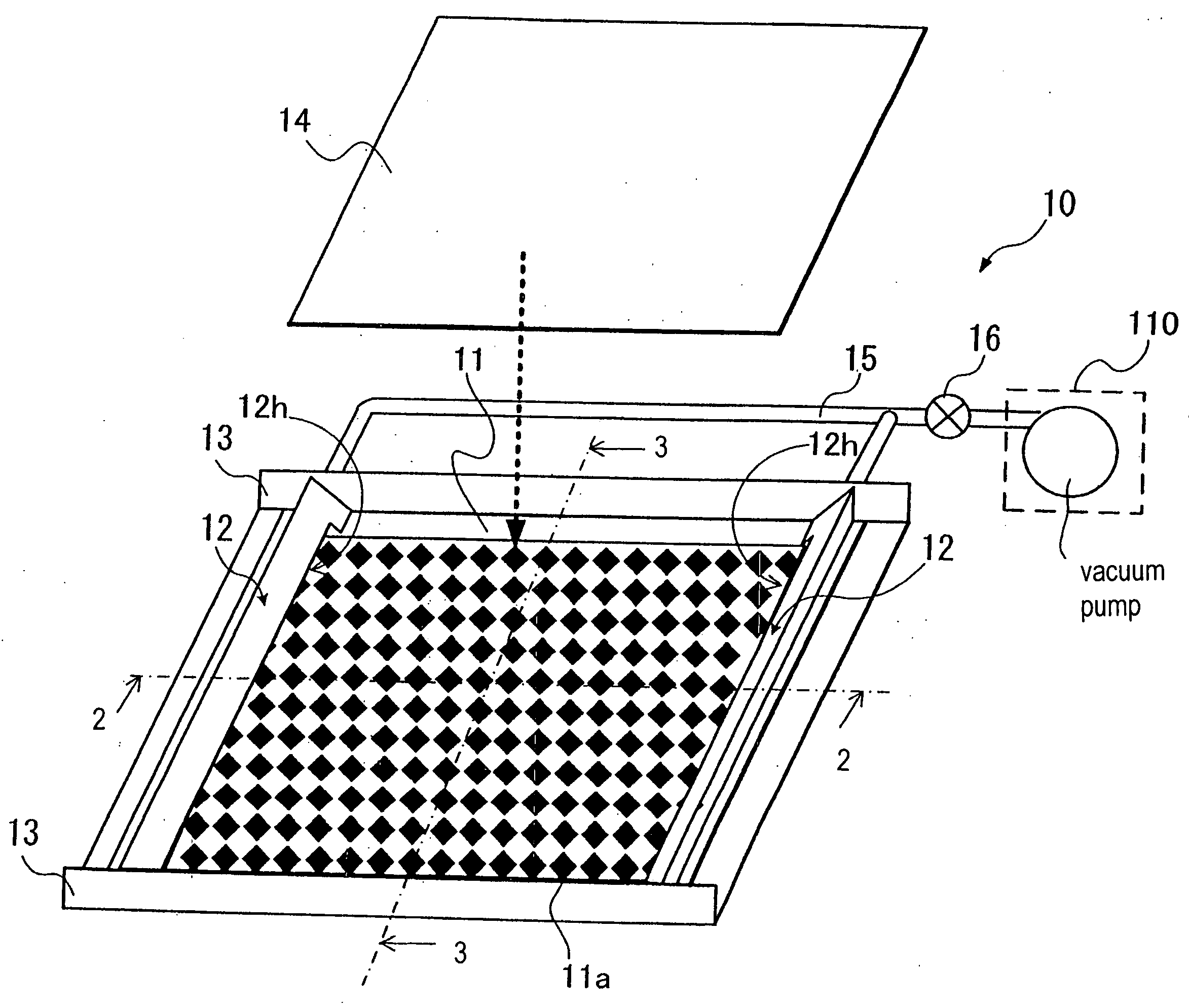
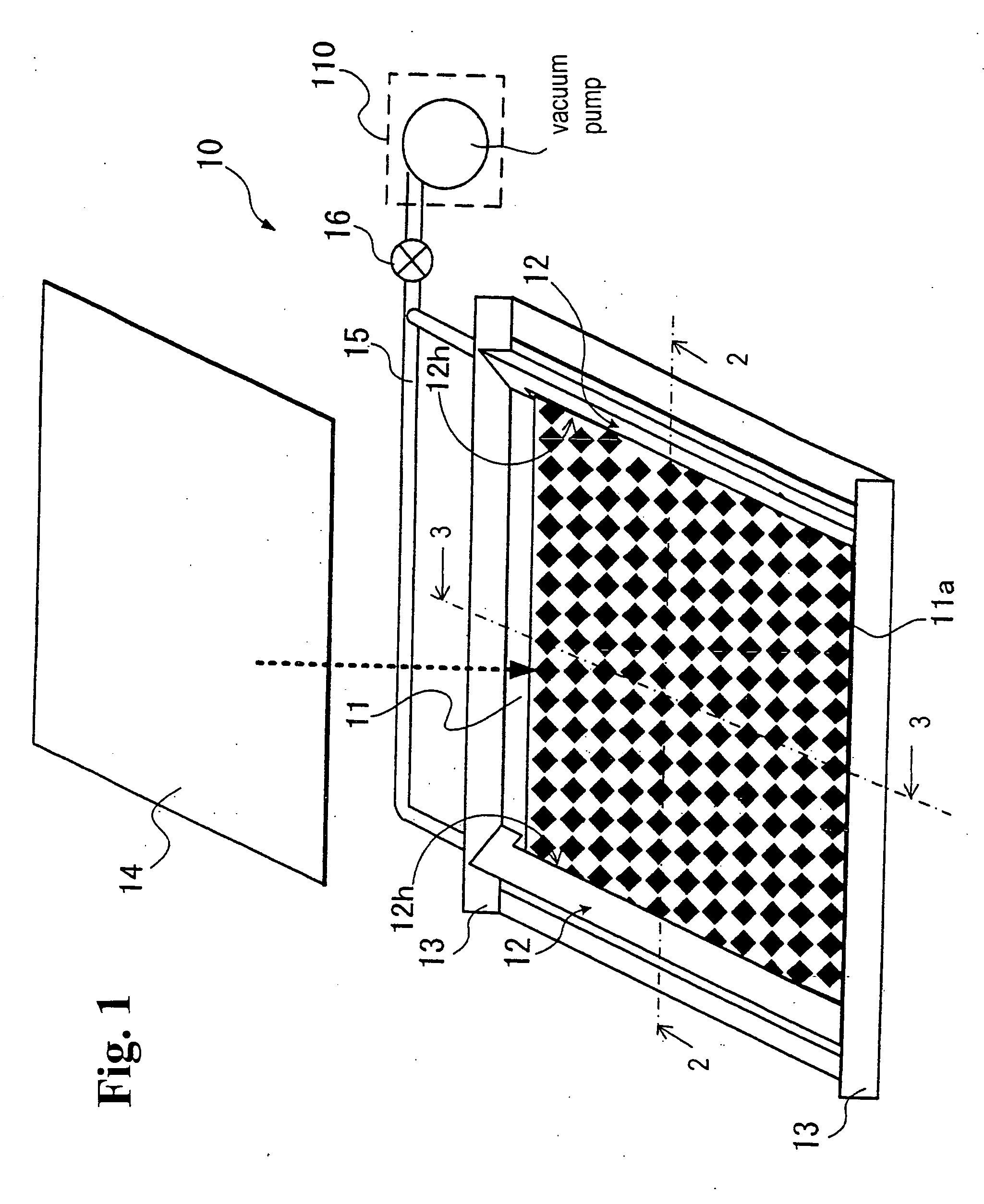
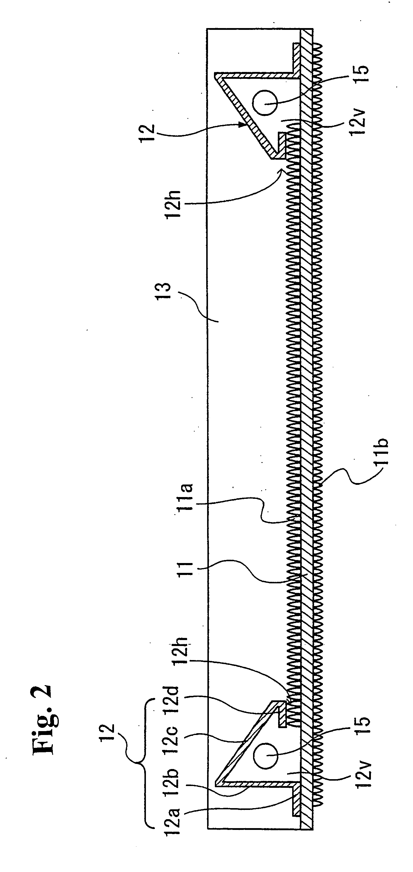
[0027] Hereunder, embodiments of the present invention will be explained in detail with reference to the accompanying drawings. FIG. 1 is a perspective view of a vacuum lamination device according to an embodiment of the present invention. FIG. 2 is a cross-sectional view taken along line 2-2 in FIG. 1. FIG. 3 is a cross-sectional view taken along line 3-3 in FIG. 1. According to an embodiment, a vacuum lamination device 10 includes a base plate 11 for placing a lamination member (referred to as a solar cell module) thereon; frame members 12 fixed on the base plate 11 and having discharge ports 12h for evacuating a processing space; plate members 13 fixed to end portions of the frame members 12 in a width direction; and a cover member 14 for hermetically sealing the processing space. The vacuum lamination device 10 further includes a discharge port 15 as a path for connecting the frame members 12 and a vacuum pump 110 through a valve 16.

[0028] The base plate 11 constitutes a bottom...


PUM

PropertyMeasurementUnit
Heightaaaaaaaaaa

Abstract

A vacuum lamination device for laminating a lamination member includes a base plate having an uneven surface contacting the lamination member for placing the lamination member, a frame member fixed to the base plate and having a discharge port for evacuating a processing space, and a cover member for hermetically sealing the processing space in the lamination process. In a vacuum lamination method, the lamination member is placed on the uneven surface, and the cover member is placed so as to cover the lamination member. Then, a gaseous material in the processing space is evacuated through the discharge port while heating the processing space.

Description

BACKGROUND OF THE INVENTION AND RELATED ART STATEMENT [0001] The present invention relates to a vacuum lamination device and a vacuum lamination method, and more particularly relates to a vacuum lamination device and a vacuum lamination method for performing a lamination process by evacuating a processing space in which a member to be laminated (hereinafter referred to as lamination member) such as a solar cell module and the like is arranged. [0002] A large amount of fossil fuel has been consumed since Industrial Revolution, and the global environment has been worsened due to air pollution and global warming by CO2. Accordingly, in recent years, environmental consciousness has been increased in the global scale. In this circumstance, solar cells have been expected to be as safe, easy to handle, and clean energy source. There are several types of solar cells including a single crystal silicon solar cell, a polycrystalline silicon solar cell, an amorphous silicon solar cell, and a co...

Claims


Application Information

Patent Timeline
IPC IPC(8): H01L31/04B29C65/00H01L31/18
CPCB32B2457/12B32B37/1018
Inventor YOKOYAMA, YASUHIRO
Owner FUJI ELECTRIC HLDG CO LTD
Why Eureka
Try Eureka