Ionizer and discharge electrode assembly to be assembled therein

a technology of ionizer and discharge electrode, which is applied in the direction of corona discharge, beam/ray focussing/reflecting arrangement, instruments, etc., can solve the problems of reducing the yield of ions, and achieve the effect of preventing deformation increasing the rigidity of the guard ring

Inactive Publication Date: 2005-06-02
KEYENCE
View PDF8 Cites 28 Cited by
  • Summary
  • Abstract
  • Description
  • Claims
  • Application Information

AI Technical Summary

Benefits of technology

[0007] A further object of the invention is to provide an ionizer capable of preventing contamination of discharge electrodes as well as a discharge electrode assembly to be assembled in the ionizer.
[0037] The guard ring has some major functions brought about by the ring main body. One of the major functions is a finger guard function to protect operator's fingers from touching the tip of the discharge electrode during replacement of a new discharge electrode, for example. Another function is to increase rigidity of the guard ring to prevent deformation of the guard ring when an operator pinches it with his / her fingers upon replacement of the discharge electrode.

Problems solved by technology

Therefore, here is the problem that the nozzles attenuate the electric field around the discharge electrodes and hence reduce the yield of ions.

Method used


Image

  • Ionizer and discharge electrode assembly to be assembled therein
  • Ionizer and discharge electrode assembly to be assembled therein
  • Ionizer and discharge electrode assembly to be assembled therein

Examples


Embodiment Construction

[0052] Some embodiments of the invention are explained below in detail with reference to the drawings.

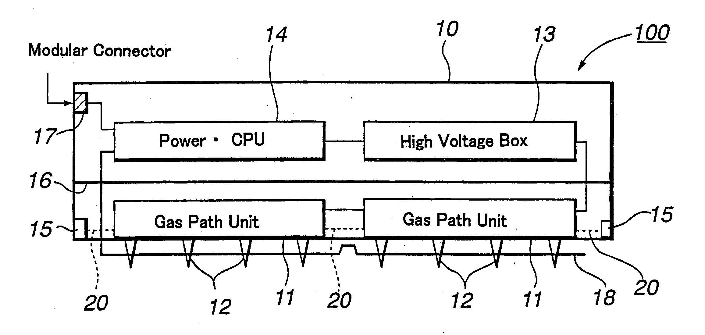
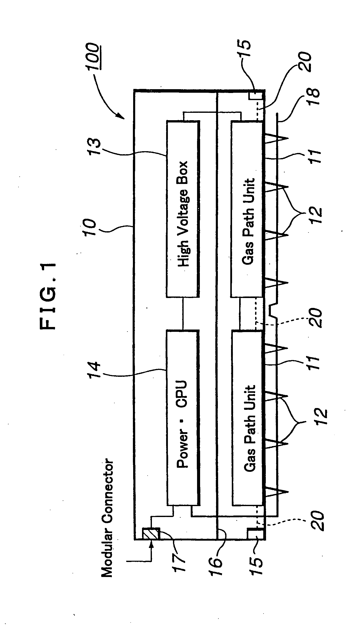
[0053]FIG. 1 shows internal layout of a discharge electrode bar 100 in an ionizer according to an embodiment of the invention. FIG. 2 shows outer appearance of the discharge electrode bar 100 in its perspective view.

[0054] The discharge electrode bar 100 has an inverted U-shaped case 10 closed upward. In the lower region inside the case 10, a plurality of gas path units 11 and a plurality of discharge electrodes 12 having sharp tips (front ends) are arranged at intervals.

[0055] In an upper region inside the case 10, a high voltage unit 13 and a control unit 14 are located. The high voltage unit 13 is contained in a seal box. The control unit 14 includes a power supply circuit, display circuit, for example, and CPU. Opposite end surfaces of the case 10, which are lengthwise perimeters of the case 10, have clean gas ports 15. Through these clean gas ports, the gas path units 11 are...


PUM


Abstract

An ionizer of a corona discharge type is configured to increase the yield of ions while minimizing contamination of a discharge electrode by foreign matters. In the ionizer, a gas path unit (11) supplied with clean gas has internal clean gas paths (50, 48) in an electrode assembly (40), and clean gas is released through each internal clean gas path (50, 48) to make a clean gas flow enclosing a front end portion of a discharge electrode (12). The electrode assembly (40) has a guard ring (46) encircling the discharge electrode (12), and the guard ring (46) has external air inlet openings (46b) permitting free passage of atmospheric air. The clean gas flow enclosing the tip of the discharge electrode (12) inhales atmospheric air through external air inlet openings (46b) of the guard ring (46) and changes to ionized air.

Description

FIELD OF THE INVENTION [0001] This invention relates to controlling static electricity in air or electric discharge from a work. More particularly, the invention relates to an ionizer and a discharge electrode assembly mounted therein. BACKGROUND OF THE INVENTION [0002] Ionizers of a corona discharge type are widely used for controlling static electricity in air, such as cleaning of clean rooms and electric discharge from floating particles, as well as electric discharge from works. [0003]FIG. 14 shows a discharge electrode bar of a currently available DC ionizer. The discharge electrode bar 1 has an elongated tubular case 2. Cylindrical nozzles 3a, 3b, each encircling a discharge electrode, are attached to the case 2 at intervals along the lengthwise direction of the case 2. [0004] In the conventional discharge electrode bar 1, a high voltage source unit 4 or a control unit 5 is located between every adjacent nozzles 3, 3, and clean gas from each nozzle 3 is supplied through a flex...

Claims


Application Information

Patent Timeline
Patent Type & Authority Applications(United States)
IPC IPC(8): H05F3/04H01J3/14H01T19/00H01T23/00
CPCH01T23/00H01T19/04H05F3/04
Inventor IZAKI, TOMOMITOKITA, YUKI
Owner KEYENCE
Why Eureka
Try Eureka