Motor for blowers

a blower and motor technology, applied in the direction of machines/engines, liquid fuel engines, magnetic circuit shapes/forms/construction, etc., can solve the problem of blower becoming bulky, and achieve the effect of low noise level of blower and high blast performan

Inactive Publication Date: 2005-06-02
JAPAN SERVO CO LTD
View PDF12 Cites 11 Cited by
  • Summary
  • Abstract
  • Description
  • Claims
  • Application Information

AI Technical Summary

Benefits of technology

[0008] In the blower motor, because the rotor tapers off toward the air inlet, air flows along the side surface of the cone-shaped rotor

Problems solved by technology

Thus, the blowe

Method used


Image

  • Motor for blowers
  • Motor for blowers
  • Motor for blowers

Examples


Embodiment Construction

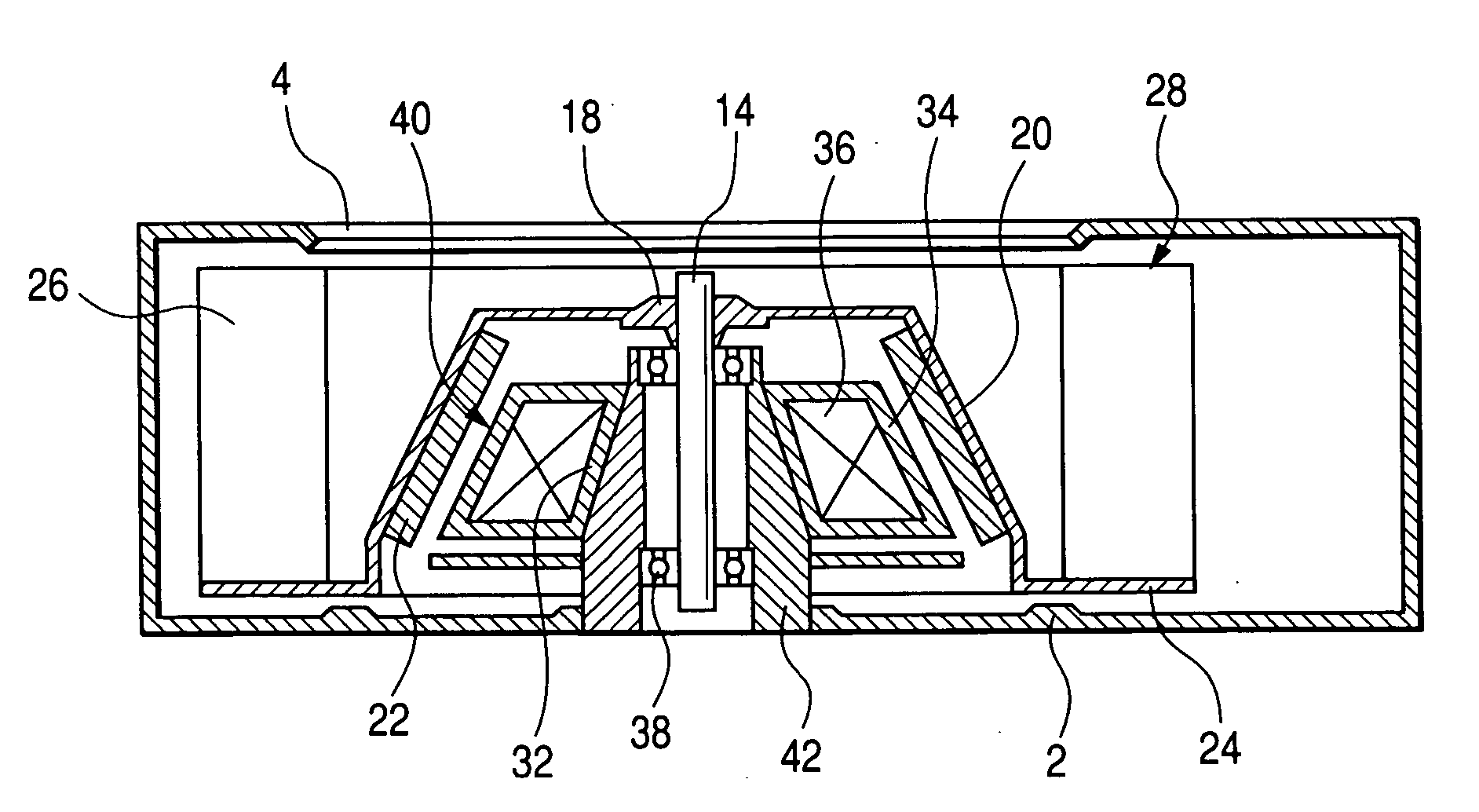
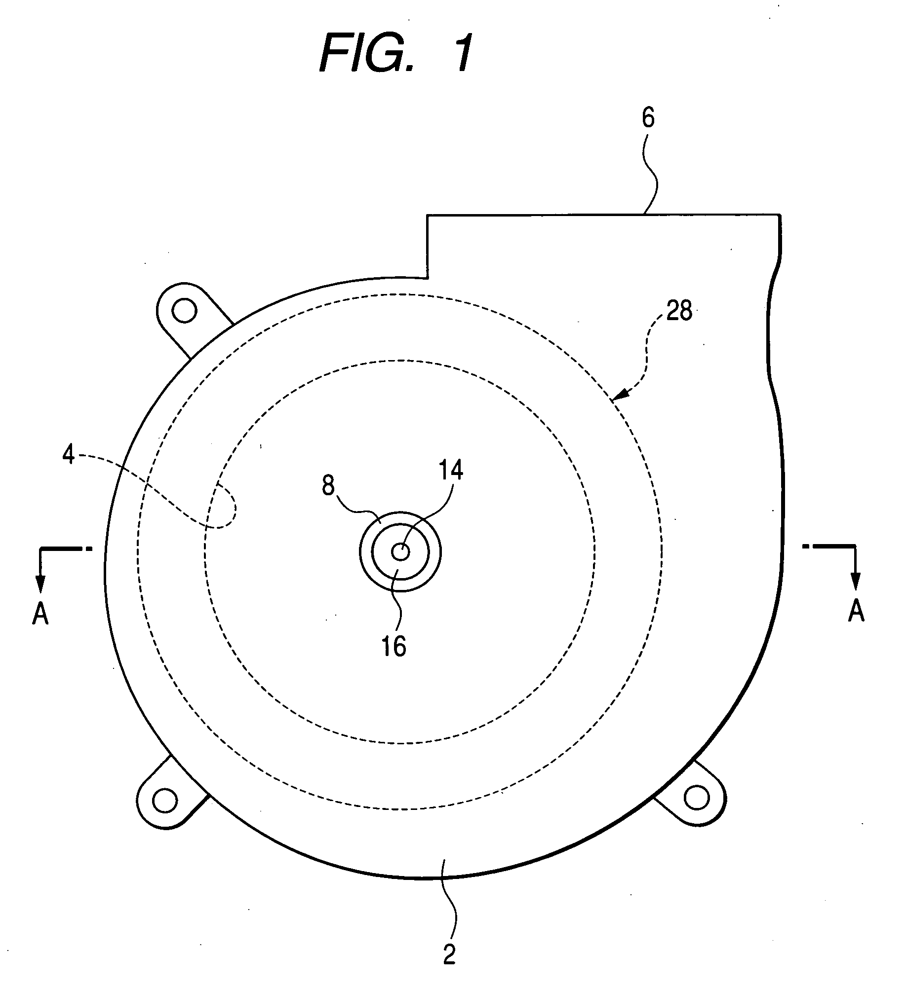
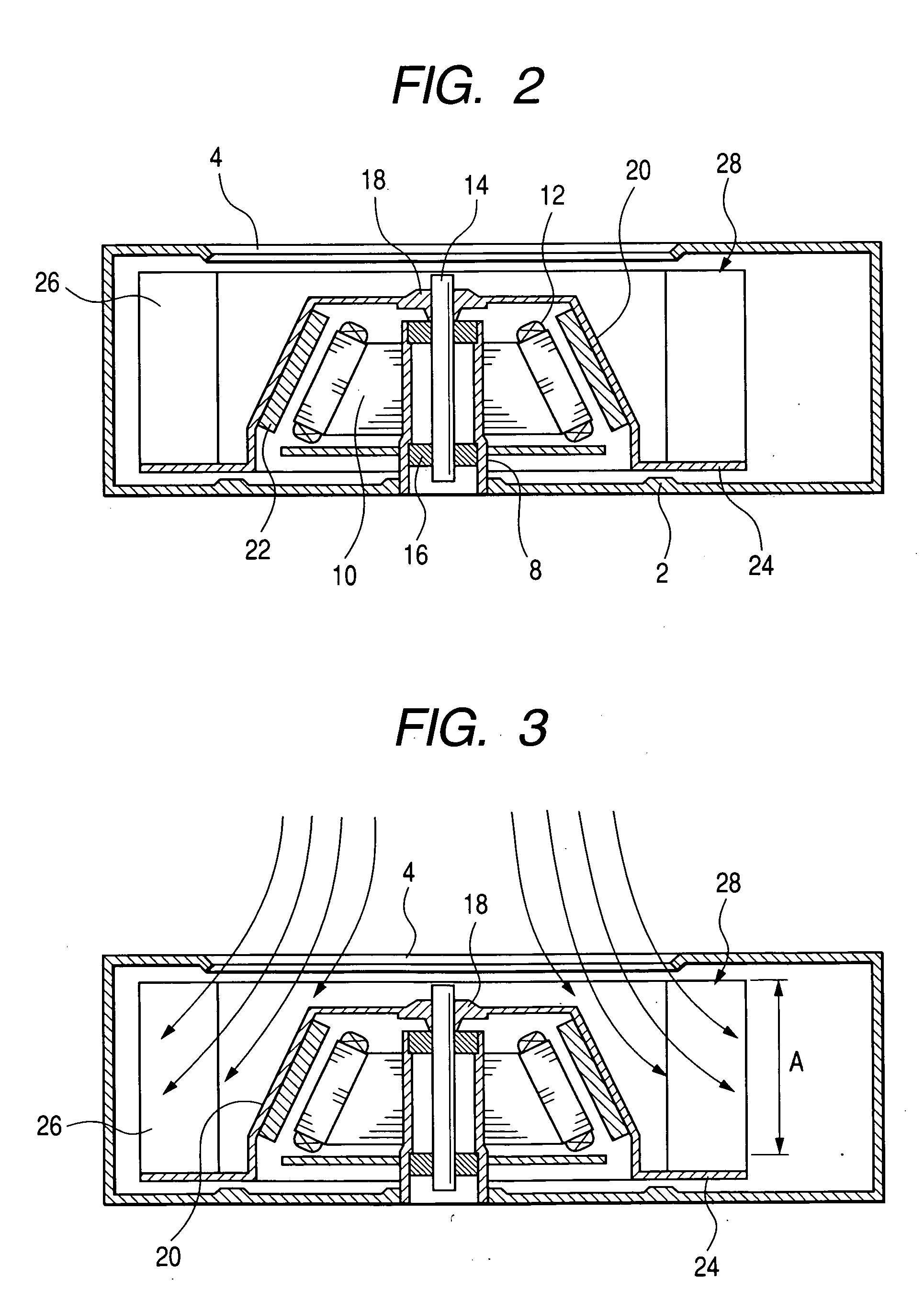
[0015] By referring to FIGS. 1 and 2, a blower fitted with a blower motor of the present invention will be described below. An air inlet 4 is provided on one sidewall of a casing 2, an outlet 6 is provided on an outer circumferential surface of the casing 2. A cylindrical housing 8 is fixed to the casing 2. A motor shaft 14 is supported in an oil-retaining plain bearing 16, which is supported in the housing 8. A boss 18 is fixed to the motor shaft 14. A rotor 20 is secured to the boss 18. A ring-like magnet 22 is fixed to an inner circumferential surface of the rotor 20. The magnet 22 is multi-polarized circumferentially. An outer circumferential surface of the rotor 20 tapers off toward the air inlet 4, or a portion of the motor shaft 14 fixing the boss 18 of the rotor 20. The ratio of the minimum outside diameter to the maximum outside diameter of the rotor 20 is 0.7 to 0.9. An inner circumferential surface of the magnet 22 tapers off toward the air inlet 4. A stator 10 is fixed t...


PUM


Abstract

A blower motor of the present invention comprises a housing, a motor shaft supported in a bearing which is supported in the housing, a rotor which is fixed to the motor shaft and tapers off toward an air inlet, a stator which is fixed to the housing and tapers off toward the air inlet, and a magnet fixed to an internal circumferential surface of the rotor.

Description

BACKGROUND OF THE INVENTION [0001] 1. Field of the Invention [0002] This invention relates to a motor for blowers. [0003] 2. Description of the Prior Art [0004] Disclosed in the prior art is a blower motor wherein the front end of the boss of the rotor is in the shape of a cone so that air can smoothly be sucked into the impeller. Thus, the blower motor improves the blast performance of blowers and lowers the blast noise levels of blowers. [0005] When the blower motor with the front end of the boss of the rotor in the shape of a cone is mounted to a blower, however, its impeller has to be elongated in the axial direction to achieve an improved blast performance of the blower fitted with the blower motor. Thus, the blower becomes bulky. SUMMARY OF THE INVENTION [0006] The object of the present invention is to provide a blower motor capable of reducing the noise level of blower and improving the blast performance of the blower without making the blower bulky. [0007] According to the p...

Claims


Application Information

Patent Timeline
IPC IPC(8): F04D29/00F04D25/06F04D29/28H02K7/14H02K9/02H02K21/12H02K21/22H02K21/24
CPCH02K7/14H02K21/12F04D25/0646H02K21/24F04D25/064H02K21/22F04D29/282
Inventor OHIWA, SHOJIYAMAZAKI, SUSUMUHIGO, ASAHI
Owner JAPAN SERVO CO LTD
Why Eureka
Try Eureka