Digital control of switching voltage regulators

a voltage regulator and digital control technology, applied in the field of switching power supplies, can solve the problems that other types of prior regulators like hysteretic mode regulators cannot be used in boost configurations, the output voltage of the buck the output voltage of the boost converter cannot be negative with respect to the input voltage, so as to achieve less signal ripple, improve stability, and improve the effect of transient respons

Active Publication Date: 2005-06-02
SEMICON COMPONENTS IND LLC
View PDF13 Cites 51 Cited by
  • Summary
  • Abstract
  • Description
  • Claims
  • Application Information

AI Technical Summary

Benefits of technology

[0013] The present invention results in a simpler controller that provides faster transient response and makes the control loop easier to stabilize than prior fully analog regulators operating in PWM mode. Furthermore, other types of prior regulators like hysteretic mode regulators cannot be used in boost configurations because of current build-up in the coil.

Problems solved by technology

Also, the output voltage of the buck converter cannot be negative.
Also, the output voltage of the boost converter cannot be negative with respect to the input voltage.
Furthermore, other types of prior regulators like hysteretic mode regulators cannot be used in boost configurations because of current build-up in the coil.
Prior digital controller designs operate in PWM and hence the output voltage accuracy / resolution is limited by the number of levels assigned to the duty cycle of the PWM pulses.

Method used


Image

  • Digital control of switching voltage regulators
  • Digital control of switching voltage regulators
  • Digital control of switching voltage regulators

Examples


Embodiment Construction

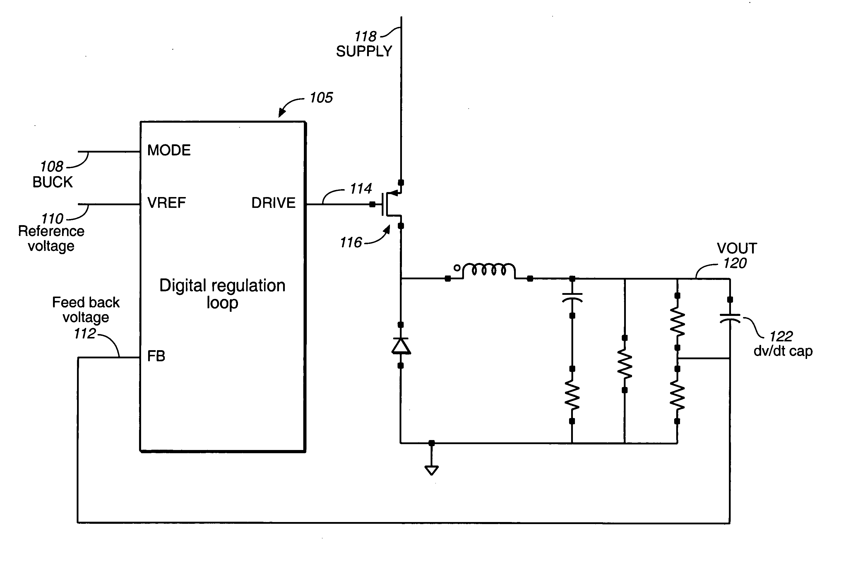
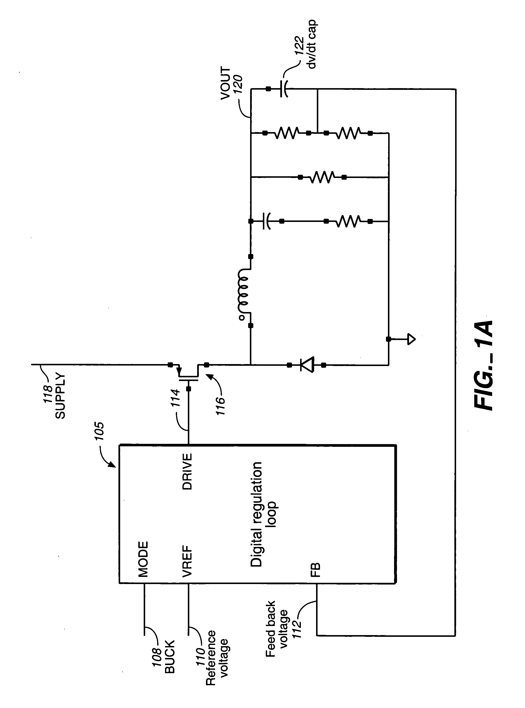
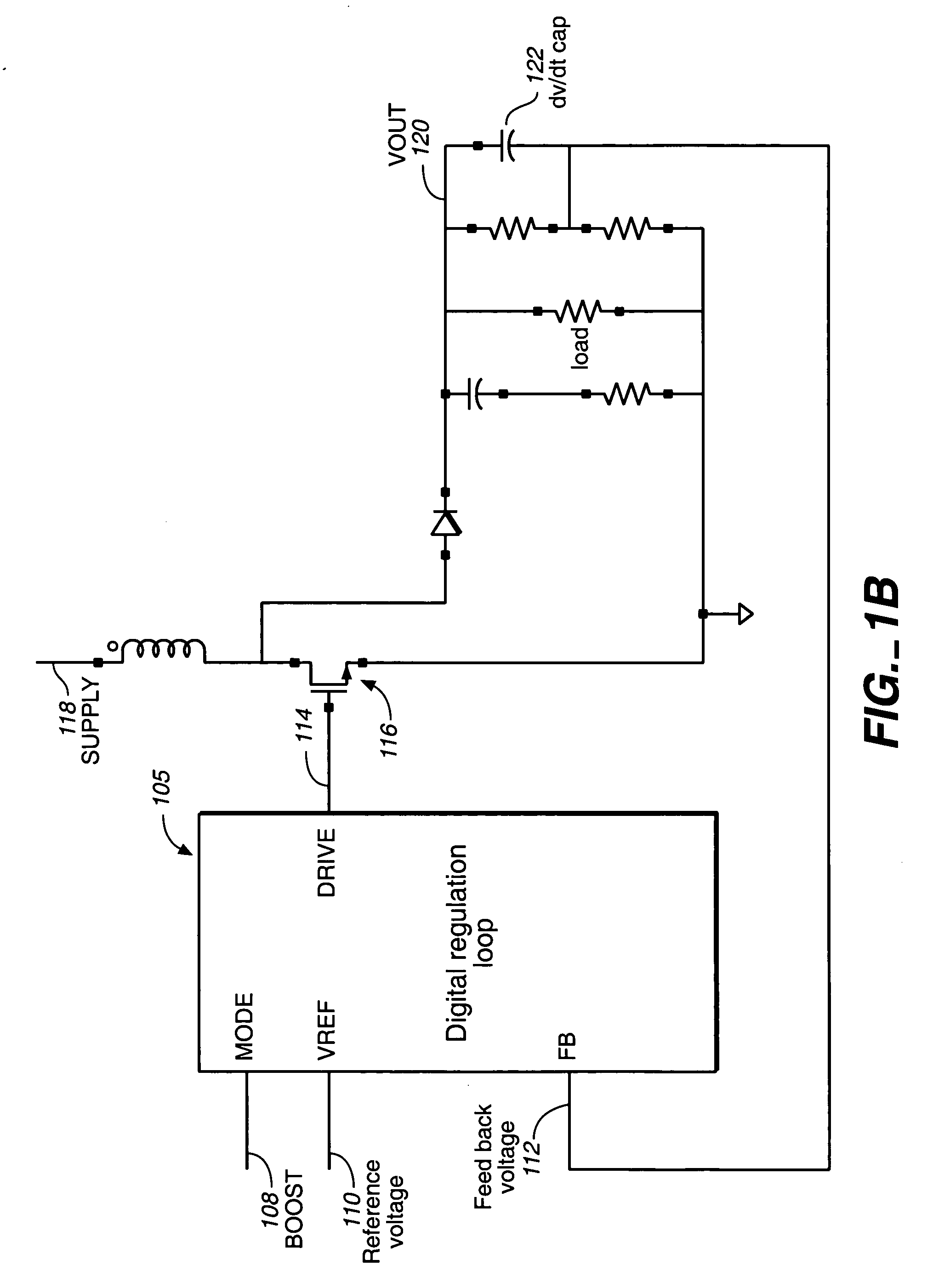
[0025] In prior converters operating in voltage mode PWM, control loop compensation is cumbersome because of the double pole of the output LC filter. In addition to this, for boost and buck-boost modes there is right-half plane zero, which degrades the phase margin further and makes voltage mode operation virtually impossible. In order to get rid of the double pole of the output LC filter, current mode PWM is often used. In this mode current in the coil is sensed and this information is used to modulate the pulse width. In the current mode converters, the LC double pole is shifted to a single pole caused by the load resistance and output capacitance, Even in current mode PWM converters, the right half plane zero still exists. In addition, current mode PWM converters utilizing pulses with about a 50% or more duty cycle created problems. The present invention, in contrast, can easily utilize such pulses. Analog controlled converters require cumbersome and complex circuitry, which is s...


PUM


Abstract

A digital control system and method for use in switching type voltage regulators measures the rate of the change and the magnitude of the output voltage to change not only the pulse width but also the frequency of the pulses. A voltage regulator according to the present invention creates a more stable output voltage and responds more quickly to sudden changes in current load than prior analog and digitally controlled systems.

Description

BACKGROUND [0001] (a) Field of the Invention [0002] The present invention relates generally to switching power supplies and more particularly to digitally controlled voltage converters. [0003] (b) Related Art [0004] In low power applications such as portable electronic devices, a buck inverter or boost converter, is generally utilized depending on the voltage of the power source and the voltage needed to power the circuitry of the portable electronic device. [0005] For example, a portable electronic device may be designed to be powered from a lithium battery that produces a supply anywhere between 4.2 volts and 3.0 volts, while CMOS integrated circuits in the device require a supply of 1.8 volts to 2.5 volts. In this example, a buck converter would be utilized to step down the battery voltage to a controlled 1.8 or 2.5 volts. If, however, the same portable electronic device were designed to be powered from a 1.5 volt battery, the device would include a boost converter to step up the...

Claims


Application Information

Patent Timeline
Patent Type & Authority Applications(United States)
IPC IPC(8): G05F1/40H02M3/157
CPCH02M3/157
Inventor PRINZ, FRANCOIS X.KOTIKALAPOODI, SRIDHAR
Owner SEMICON COMPONENTS IND LLC
Why Eureka
Try Eureka