Remote control having a display with multi-function EL segments

a multi-function, remote control technology, applied in transmission systems, instruments, computing, etc., can solve the problem of increasing the overall manufacturing cost of universal remote control, and achieve the effect of reducing the manufacturing cos

Active Publication Date: 2005-06-02
UNIVERSAL ELECTRONICS INC
View PDF18 Cites 70 Cited by
  • Summary
  • Abstract
  • Description
  • Claims
  • Application Information

AI Technical Summary

Benefits of technology

[0005] In accordance with this and other needs, the following describes a universal remote control having an EL display with multi-function EL segments that can be selectively illuminated in various combinations to provide multiple remote control user interfaces. To this end, the multi-function EL segments each include one or more complete function key images and / or fragments (which may be contiguous or non-contiguous fragments of the EL display) of complete function key images whereby one or more of the EL segments may be illuminated to present multiple, different remote control user interfaces each having one or more complete function key images. Specifically, a complete function key image presented as part of a remote control user interface may be a complete key image that was included as part of an illuminated EL segment or may be formed by a combination of function key image fragments included as part of multiple illuminated EL segments. In this manner, the described universal remote control EL display has the advantage of minimizing the number of EL segments required to present multiple remote control user interfaces and, accordingly, has a relatively reduced cost of manufacture. Additional advantages, features, properties and relationships of this improved universal remote control EL display will be obtained from the following detailed description and accompanying drawings which set forth illustrative embodiments which are indicative of the various ways in which the principles thereof may be employed.

Problems solved by technology

While a universal remote control having an EL display that can be selectively illuminated to provide multiple remote control user interfaces is desirable, it is seen that increasing the number of individually illuminable EL segments in the EL display also increases the overall manufacturing cost of the universal remote control.

Method used


Image

  • Remote control having a display with multi-function EL segments
  • Remote control having a display with multi-function EL segments
  • Remote control having a display with multi-function EL segments

Examples


Embodiment Construction

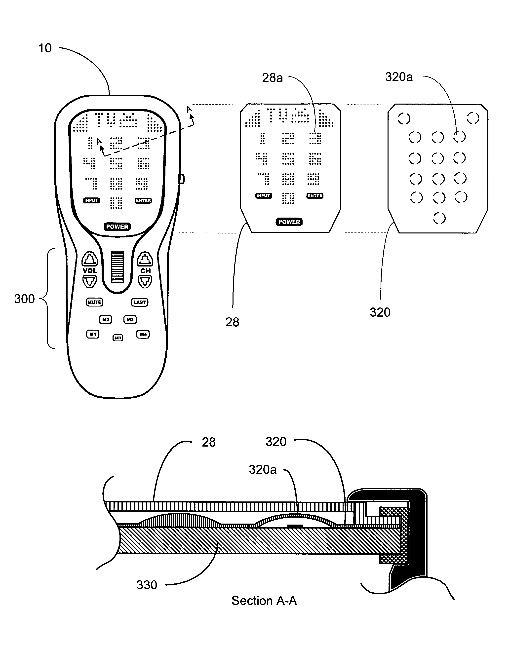
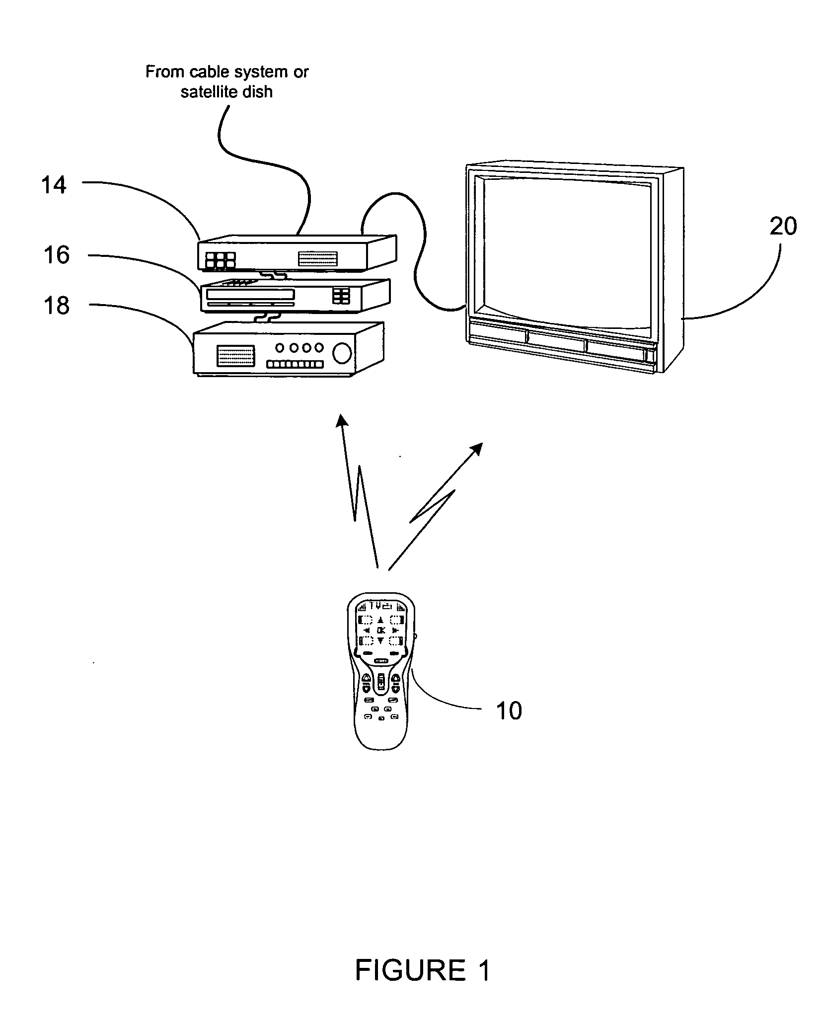
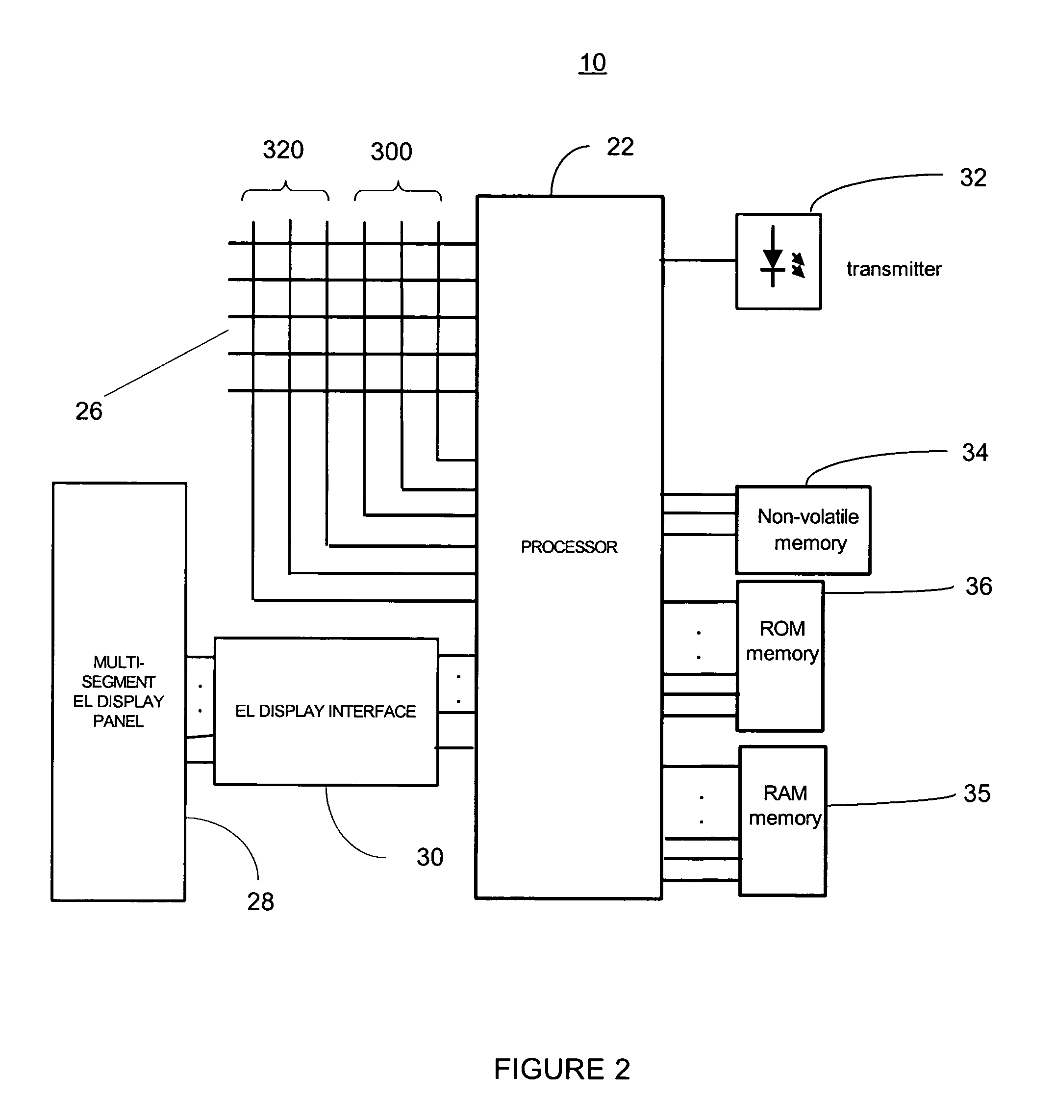
[0013] With reference to the figures, wherein like reference numerals refer to like elements, a universal remote control 10 having an EL display for presenting multiple remote control user interfaces is described. In this regard, each of the multiple remote control user interfaces provides a user with the ability to use the universal remote control 10 to command functional operations of one or more appliances of various types and various manufacturers. For example, the universal remote control 10 may include a mechanism, e.g., one or more device mode keys, a scroll wheel, navigation keys, or the like, for placing the universal remote control 10 into an operating mode for transmitting commands that are appropriate for the one or more appliances that have been assigned to or setup for that operating mode. In connection with being placed into a particular operating mode, one or more segments in the EL display may be selectively illuminated, in a manner described hereinafter, to present...


PUM


Abstract

An EL display is provided with EL segments which are individually illuminable and which include one or more complete function key images and/or fragments of complete function key images. One or more of the EL segments may thus be illuminated to present multiple, different user interfaces each having one or more complete function key images. A complete function key image presented as part of a user interface may be a complete key image that was included as part of an illuminated EL segment or may be formed by a combination of key image fragments included as part of multiple illuminated EL segments.

Description

BACKGROUND [0001] This invention relates generally to devices having displays and, more particularly, relates to a remote control having a display with multi-function electroluminescent (“EL”) segments. [0002] Devices having EL displays are known in the art. By way of example only, PCT patent application WO 00 / 72638, entitled “electroluminescent display,” discloses an EL display comprised of a transparent front-electrode, rear electrodes, and a layer of electroluminescent material located between the first and second electrodes. Conductive tracks are electrically connected to the rear electrodes and supply a driving voltage for the electroluminescent material to the rear electrodes. A backplane layer is provided between the electroluminescent material layer and the conductive tracks are electrically connected to the front electrode, such that the potential difference across the electroluminescent material layer in the region of the conductive tracks is substantially zero. In this wa...

Claims


Application Information

Patent Timeline
Patent Type & Authority Applications(United States)
IPC IPC(8): G08CG08C17/02G08C23/04G09G5/00G09G5/08
CPCG08C23/04G08C17/02
Inventor GATES, STEPHEN BRIAN
Owner UNIVERSAL ELECTRONICS INC
Why Eureka
Try Eureka