
Light-emitting diode and backlight system using the same

a backlight system and light-emitting diode technology, applied in the direction of discharge tube luminescnet screens, instruments, lighting and heating apparatus, etc., to achieve the effect of high brightness without any dark areas

Inactive Publication Date: 2005-06-02
GOLD CHARM LTD
View PDF15 Cites 101 Cited by
  • Summary
  • Abstract
  • Description
  • Claims
  • Application Information

AI Technical Summary

Benefits of technology

[0010] Another object of the present invention is to provide a backlight system yielding uniform illumination derived from light beams originally emitted from one or more LEDs having large radiation angles.
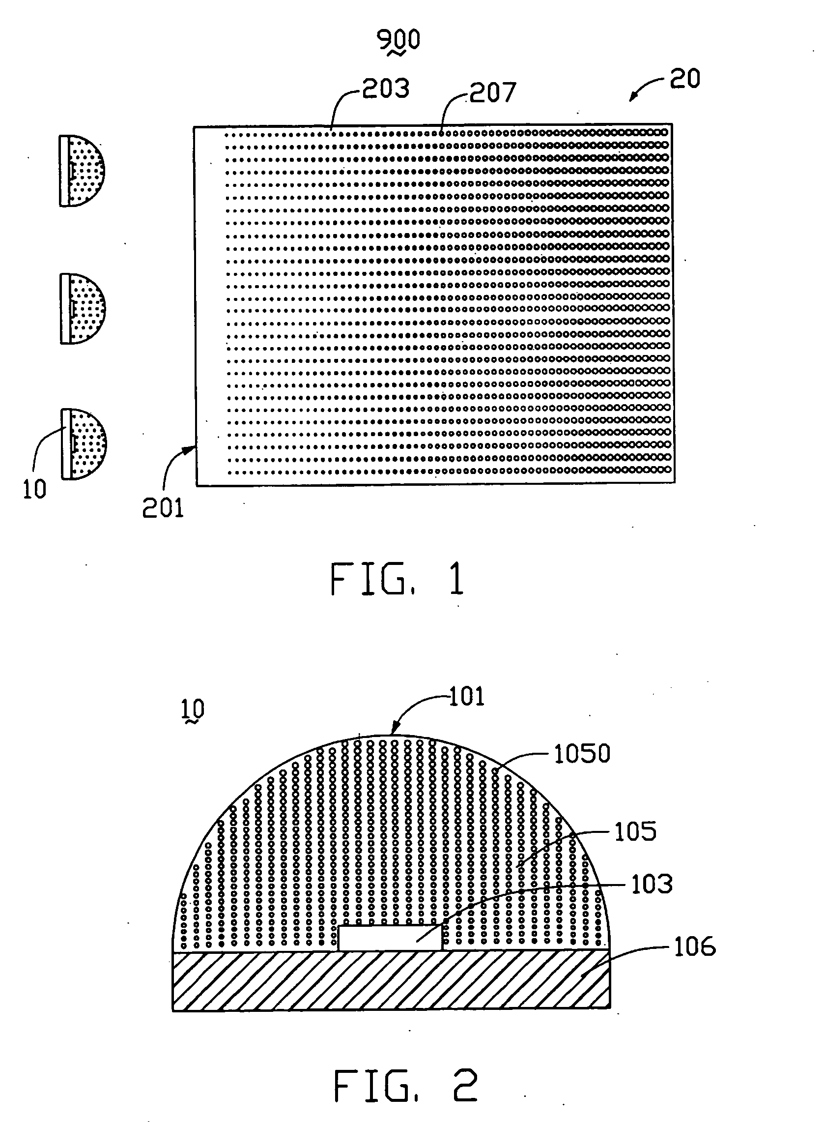
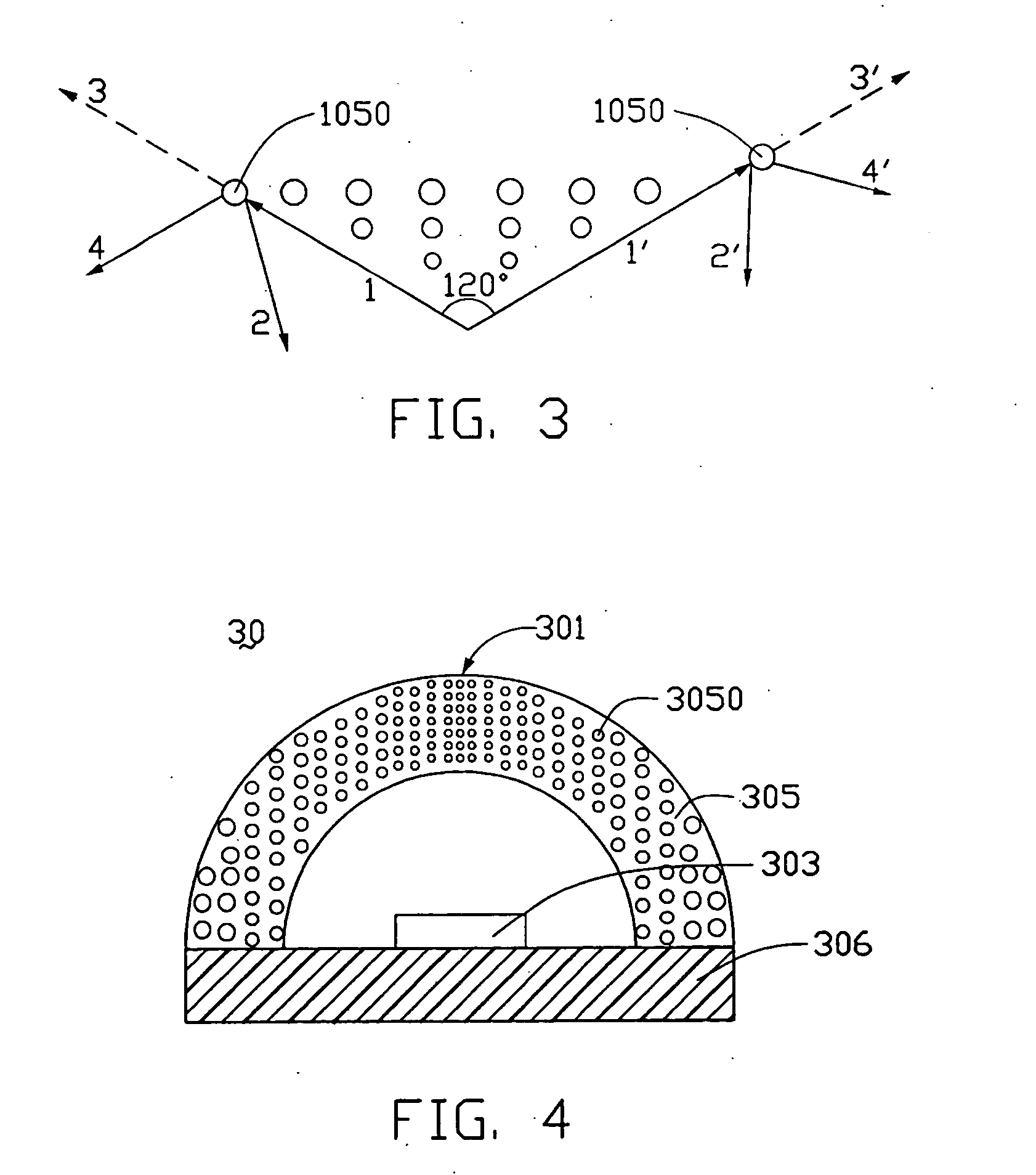
[0011] According to a first aspect of the present invention, there is provided an LED comprising a chip body, an encapsulation can surrounding the chip body, and a base supporting the encapsulation can and the chip body thereon. A plurality of fluorescent particles is contained in the encapsulation can, for scattering light emitted from the chip body. With these diffusing particles, light beams from the chip body are diffused and attain wider radiation angles.
[0012] In order to achieve the second objective, there is provided a backlight system comprising a light guide plate, and a plurality of LEDs according to the above-described LED. The LEDs are disposed adjacent to the light guide plate. Light beams having wide radiation angles are emitted from the LEDs and enter the light guide plate. This enables a light emitting surface of the light guide plate to have highly uniform brightness without any dark areas.

Problems solved by technology

Liquid crystal displays are commonly used as the display device for compact electronic apparatuses, because they not only display good quality images using little power but also are very thin.

Method used


Image

  • Light-emitting diode and backlight system using the same
  • Light-emitting diode and backlight system using the same
  • Light-emitting diode and backlight system using the same

Examples


Embodiment Construction

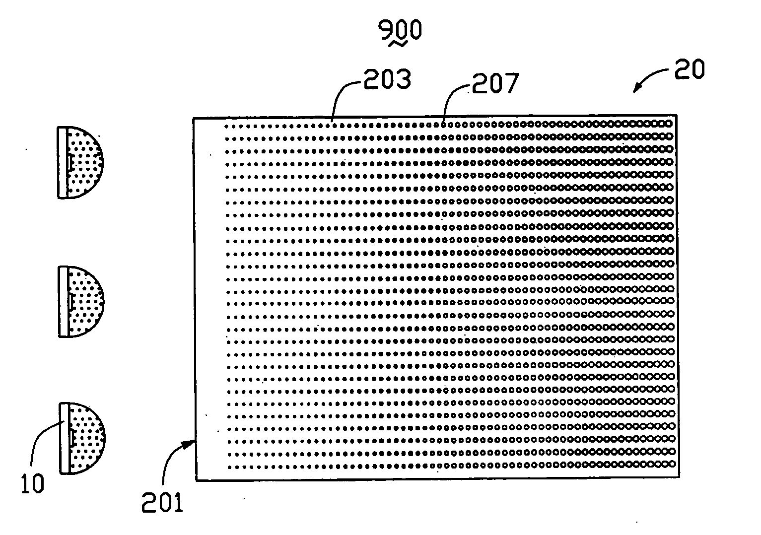
[0020] Referring to FIG. 1, a backlight system 900 in accordance with the first preferred embodiment of the present invention includes a plate-like light guide member 20 in this embodiment and a plurality of LEDs 10 as a light source. The LEDs 10 provide light beams to the light guide plate 20, which redirects the light beams. Thus the light guide plate 20 functions to convert a series of point light sources into a uniform surface light source.

[0021] The light guide plate 20 is made of transparent material such as acrylic resin, polycarbonate resin, polyvinyl chloride, or glass. The light guide plate 20 is a rectangular sheet, or alternatively may be generally cuneiform. The light guide plate 20 includes a light incident surface 201, an emitting surface (not labeled) connected with the light incident surface 201, and a bottom surface 203 opposite to the emitting surface. The light incident surface 201 of the light guide plate 20 receives light beams from the LEDs 10. The emitting s...


PUM


Abstract

A light-emitting diode (LED) (10) includes a chip body (103), an encapsulation can (105) surrounding the chip body, and a base (106) supporting the encapsulation can and the chip body thereon. Numerous fluorescent particles (1050) are provided in the encapsulation can. With the fluorescent particles, light beams from the chip body are diffused and attain wider irradiation angles. A backlight system (900) includes a light guide plate (20), and a number of the above-described LEDs disposed adjacent to the light guide plate. Light beams having wide irradiation angles are emitted from the LEDs and enter the light guide plate. This enables a light emitting surface of the light guide plate to have highly uniform brightness.

Description

CROSS-REFERENCE TO RELATED APPLICATIONS [0001] This application is related to a copending U.S. patent application ______ entitled “LIGHT-EMITTING DIODE AND BACKLIGHT SYSTEM USING THE SAME”, filed on the same day with the same applicants and assignee as the invention. The disclosure of the above identified applications is incorporated herein by reference.BACKGROUND OF THE INVENTION [0002] 1. Field of the Invention [0003] The present invention relates to a light-emitting diode (LED), and especially to an LED used in a backlight system for a device such as a liquid crystal display. [0004] 2. Description of the Prior Art [0005] Liquid crystal displays are commonly used as the display device for compact electronic apparatuses, because they not only display good quality images using little power but also are very thin. However, the liquid crystals in a liquid crystal display do not emit any light themselves. The liquid crystals have to be lit up by a light source so as to clearly and shar...

Claims


Application Information

Patent Timeline
IPC IPC(8): F21V7/04F21V8/00H01J1/62H01J63/04H01L33/50
CPCG02B6/0023G02B6/0036H01L2933/0091H01L33/508G02B6/0061
Inventor LEU, CHARLESYU, TAI-CHERNGCHEN, GA-LANE
Owner GOLD CHARM LTD
Learn More