
Reflector device and method of manufacturing same

a technology of reflectors and components, applied in the direction of lighting support devices, lighting and heating apparatus, instruments, etc., can solve the problems of increasing manufacturing costs, unable to modularize prior art manufacturing, and prior art that is difficult to put into practice in industry, so as to reduce the cost of manufacturing. , the effect of mass production

Inactive Publication Date: 2005-06-02
HAYASHIBARA BIOCHEMICAL LAB INC
View PDF6 Cites 25 Cited by
  • Summary
  • Abstract
  • Description
  • Claims
  • Application Information

AI Technical Summary

Benefits of technology

[0005] It is an object of the present invention to provide a reflector belt and method of manufacturing same wherein advantages of being ease of mass production and reduced much manufacturing cost are attained for upstream manufacturer due to the provision of modular components.
[0006] It is another object of the present invention to provide a reflector belt and method of manufacturing same wherein no additional equipment and no additional stock material and components are required in the manufacturing process due to the provision of modular components and thus D.I.Y manufacturing and saving manufacturing cost are readily accomplished in downstream manufacturer.
[0007] It is further object of the present invention to provide a reflector belt and method of manufacturing same wherein each reflector device is provided with waterproof and airtight for enabling the reflector device to employ in an environment requiring a highly safe operating standard.

Problems solved by technology

However, it is impossible of manufacturing the prior art in a modularized, mass production since the coupling, wiring and checking of illuminators, wires, power switch, power supply and other electrical components and the stitching process are tedious and much time consuming.
Hence, the prior art finds it hard of putting into practice in industry.
This inevitably will increase the manufacturing cost and lower the production.
This further complicates the manufacturing process.
To the worse one such reflector belt having a poor waterproof or airtight capability may cause danger (e.g., spark or explosion caused by exposing wires, flash controller, and illuminators to air having gas or other inflammable articles) when it is used in an environment requiring a highly safe operating standard.

Method used


Image

  • Reflector device and method of manufacturing same
  • Reflector device and method of manufacturing same
  • Reflector device and method of manufacturing same

Examples


Embodiment Construction

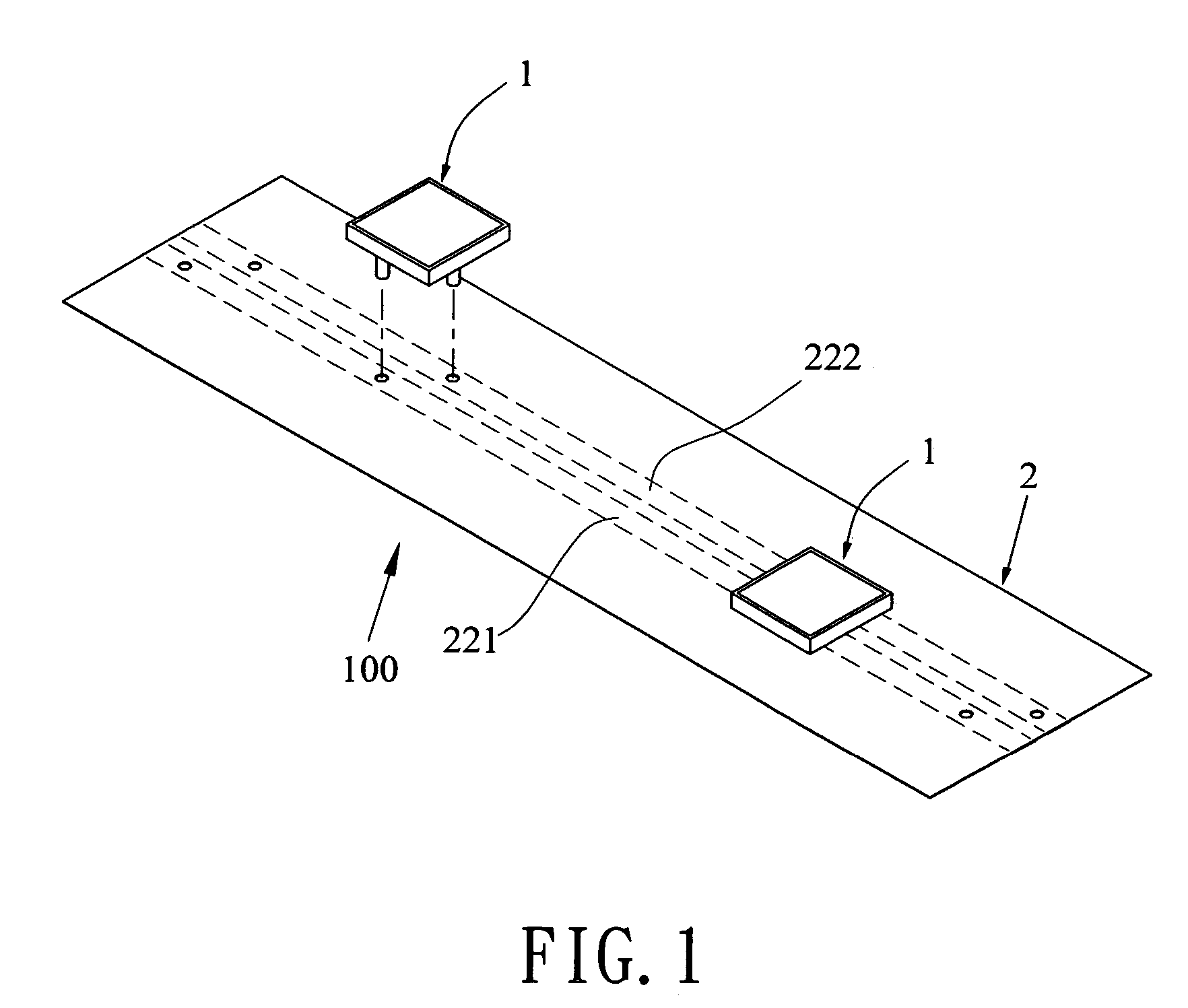
[0037] Referring to FIG. 1, there is shown a reflector device constructed in accordance with the invention. The reflector device comprises a belt unit 2 and a lamp unit 1 secured onto the belt unit 2 so as to form a reflector device 100. The reflector device 100 has the advantages of being waterproof, airtight, and used as warning means. The reflector device 100 finds an application of stitching to clothes, mounting to a warning device, or the like. Each component of the lamp unit 1 and the belt unit 2 will be described in detail below.

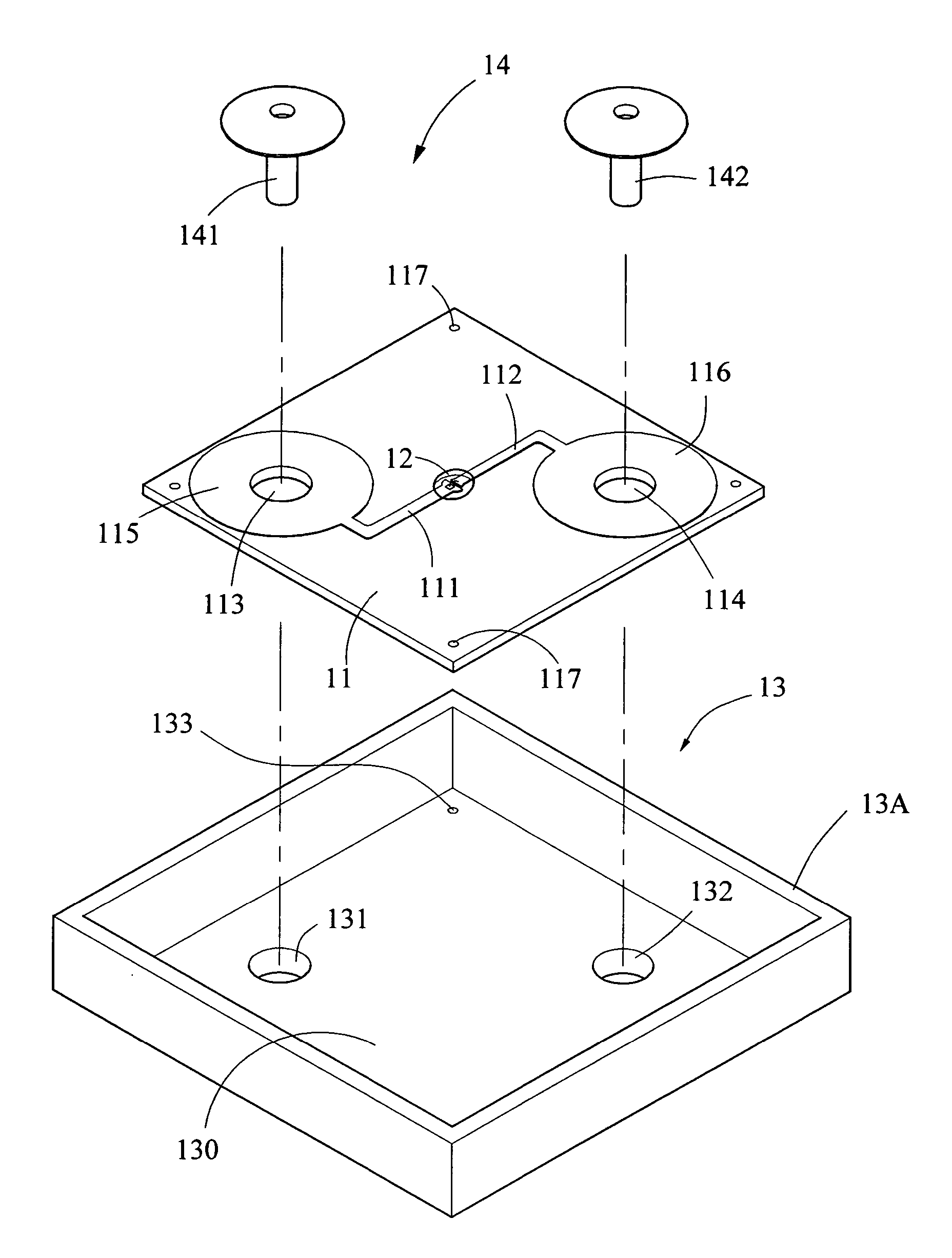
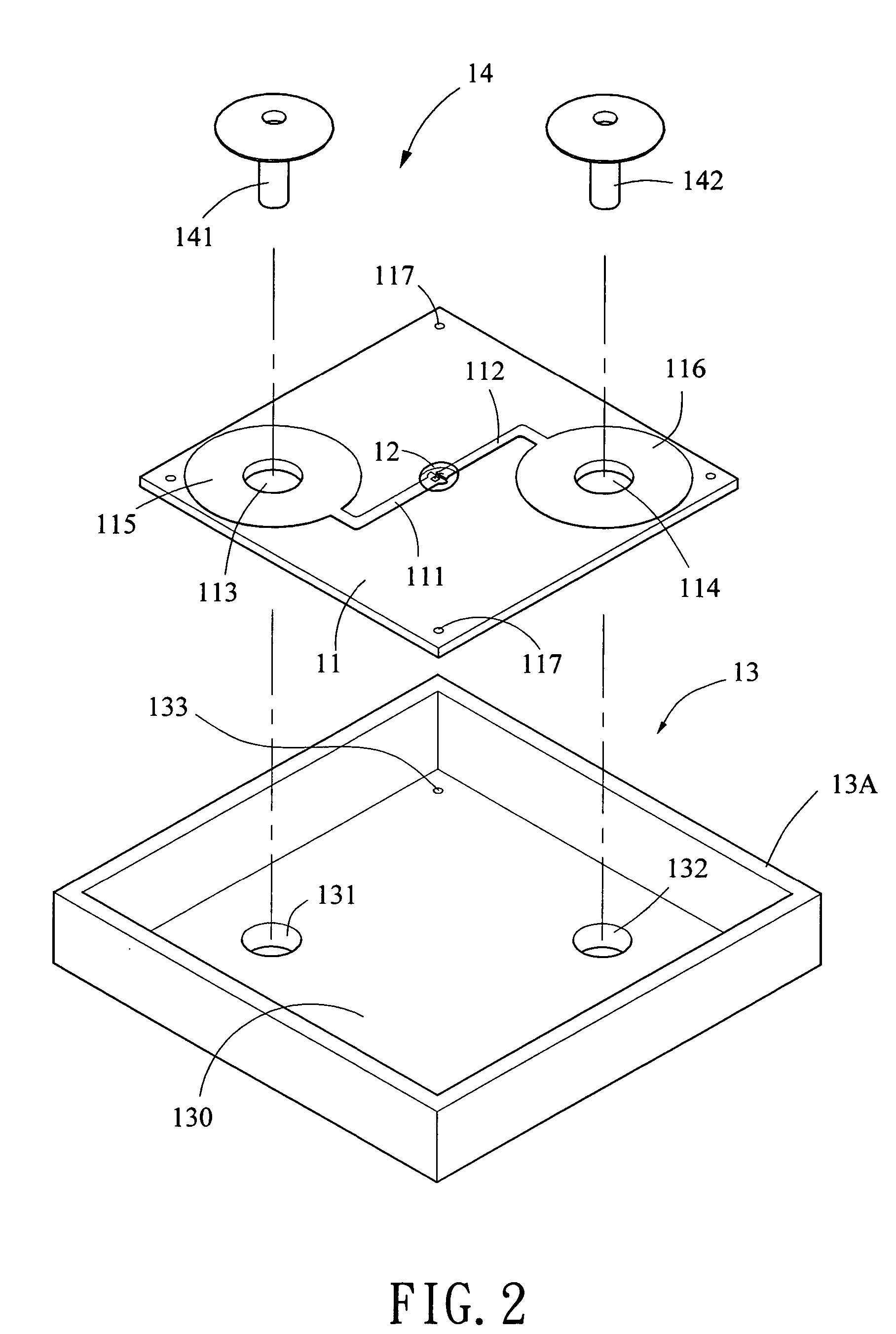
[0038] Referring to FIGS. 2 to 4, the lamp unit 1 comprises a base 11, a LED (light-emitting diode) lamp 12, a seat assembly 13, and two or more rivets including rivets 141 and 142. The base 11 comprises two electric wires 111, 112 and two apertures 113, 114. A contact 115 is provided at the aperture 113 and another contact 116 is provided at the aperture 114 so as to electrically couple to the wires 111 and 112 respectively as a portion of the elect...


PUM


Abstract

Disclosed is a reflector devise and method manufacturing same. The reflector device comprises a lamp unit comprising a seat assembly, a rivet assembly in the seat assembly, the rivet assembly including rivets projected from an underside of the seat assembly, and a LED lamp in the seat assembly, the LED lamp being electrically coupled to the rivet assembly; and a belt unit comprising an insulating layer and a conductive layer sealed by the insulating layer. The conductive layer comprises conductors and the insulating layer comprises sets of holes along the conductive layer so that the rivets are adapted to pass through the holes into the conductive layer to fasten and electrically connect the lamp and the belt units together. The invention has advantages of mass production and being waterproof and airtight.

Description

BACKGROUND OF THE INVENTION [0001] 1. Field of the Invention [0002] The present invention relates to reflector devices and more particularly to a modularized reflector device having advantages of being ease of mass production and being waterproof and airtight, and method of manufacturing same. [0003] 2. Description of Related Art [0004] A prior reflector belt (or reflector device) comprises a plurality of illuminators electrically coupled together by wires, a switch, a power supply, a flash controller all coupled to the illuminators, and a reflective strip (or waterproof belt) for enclosing the above components. The reflector belt is typically stitched to a clothes or the like. Such design has been disclosed in Taiwanese Patent Published Nos. 355,642 and 383,121. However, it is impossible of manufacturing the prior art in a modularized, mass production since the coupling, wiring and checking of illuminators, wires, power switch, power supply and other electrical components and the s...

Claims


Application Information

Patent Timeline
Patent Type & Authority Applications(United States)
IPC IPC(8): F21K99/00F21V17/00H01L33/48H01L33/62H01R4/06
CPCF21K9/00H01L33/483H01L33/62H01R4/06H01L2924/0002H01R12/68H01L2924/00F21K9/90
Inventor LIN, YUAN
Owner HAYASHIBARA BIOCHEMICAL LAB INC
Learn More