Apparatus and method for performing fast fibre channel write operations over relatively high latency networks

Active Publication Date: 2005-06-02
CISCO TECH INC
View PDF72 Cites 105 Cited by
  • Summary
  • Abstract
  • Description
  • Claims
  • Application Information

AI Technical Summary

Benefits of technology

[0010] To achieve the foregoing and other objectives and in accordance with the purpose of the present invention, an apparatus and method to improve the performance of a SCSI write over a high latency network is provided. The apparatus includes a first Switch close to the initiator in a first SAN and a second Switch close to the target in a second SAN. In various embodiments, the two Switches are border switches connecting their respective SANs to a relatively high latency network between the two SANs. In addition, the initiator can be either directly connected or indirectly connected to the first Switch in the first SAN. The target can also be either directly or indirectly connected to the second Switch in the second SAN. During operation, the method includes the first Switch sending Transfe

Problems solved by technology

However, since maintaining a SAN across long distances is expensive, the organization may rely on the Internet Protocol (IP) over another inter-SAN link such as Gigabit Ethernet, SONET, ATM, wave division multiplexing, etc. to connect the SANs.
In other words, even if multiple Switches need to be spanned to complete the access, the speed of the individual Switches is so fast that the latency time is typically very small.
In situations with a high latency inter-SAN link, however, the access time of a write operation between a Host in one SAN and a storage device in a remote SAN will suffer or deteriorate.
The latency may result from the speed of the link, the distance between the Host a

Method used


Image

  • Apparatus and method for performing fast fibre channel write operations over relatively high latency networks
  • Apparatus and method for performing fast fibre channel write operations over relatively high latency networks
  • Apparatus and method for performing fast fibre channel write operations over relatively high latency networks

Examples


Example

[0018] Like reference numbers refer to like elements in the figures.

DETAILED DESCRIPTION OF THE INVENTION

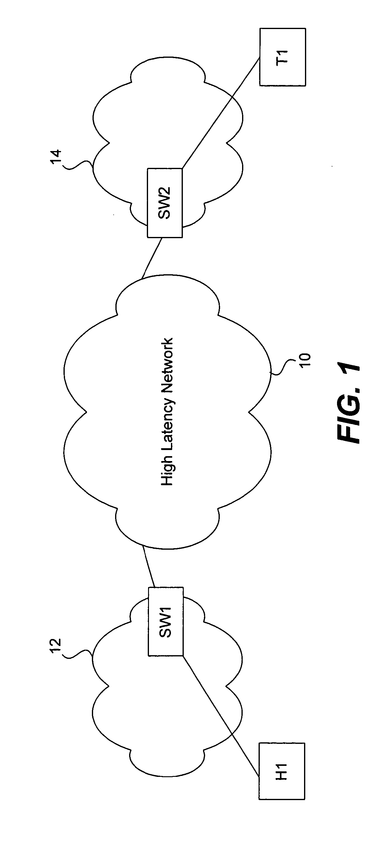
[0019] Referring to FIG. 1, a diagram of a high latency inter-SAN network 10 connecting a Host H1 in a first SAN 12 and a target storage device T1 in a second SAN 14 is shown. The Host H1 is coupled to the high latency network 10 through a first switch SW1 in SAN 12. The target storage device T1 is coupled to the network 10 through a second switch SW2. The switches SW1 and SW2 are considered “border” switches since they are positioned at the interface of the network 10 and the SANs 12 and 14 respectively. According to various embodiments, the Host H1 and target T1 may be either directly connected to switches SW1 and SW2 or connected indirectly through any number of intermediate switches respectively. The network 10 may use the Internet Protocol (IP) for example over an inter-SAN link such as Gigabit Ethernet, SONET, ATM, wave division multiplexing, etc. to connect the SANs 12 a...


PUM


Abstract

A method and apparatus to improve the performance of a SCSI write over a high latency network. The apparatus includes a first Switch close to the initiator in a first SAN and a second Switch close to the target in a second SAN. In various embodiments, the two Switches are border switches connecting their respective SANs to a relatively high latency network between the two SANs. In addition, the initiator can be either directly connected or indirectly connected to the first Switch in the first SAN. The target can also be either directly or indirectly connected to the second Switch in the second SAN. During operation, the method includes the first Switch sending Transfer Ready (Xfr_rdy) frame(s) based on buffer availability to the initiating Host in response to a SCSI Write command from the Host directed to the target. The first and second Switches then coordinate with one another by sending Transfer Ready commands to each other independent of the target's knowledge. The second switch buffers the data received from the Host until the target indicates it is ready to receive the data. Since the Switches send frames to the initiating Host independent of the target, the Switches manipulate the OX_ID and RX_ID fields in the Fibre Channel header of the various commands associated with the SCSI Write. The OX_ID and RX_ID fields are manipulated so as to trap the commands and so that the Switches can keep track of the various commands associated with the SCSI write.

Description

FIELD OF THE INVENTION [0001] The present invention relates generally to network communications, and more particularly, to an apparatus and method for performing fast Fibre Channel write operations over relatively high latency networks. BACKGROUND OF THE INVENTION [0002] With the increasing popularity of Internet commerce and network centric computing, businesses and other organizations are becoming more and more reliant on information. To handle all of this data, storage area networks or SANs have become very popular. A SAN typically includes a number of storage devices, a plurality of Hosts, and a number of Switches arranged in a Switching Fabric that connects the storage devices and the Hosts. [0003] Most SANs rely on the Fibre Channel protocol for communication within the Fabric. For a detailed explanation of the Fibre Channel protocol and Fibre Channel Switching Fabrics and Services, see the Fibre Channel Framing and Signaling Standard, Rev 1.90, International Committee for Inf...

Claims


Application Information

Patent Timeline
IPC IPC(8): G06F3/06H04LH04L12/26H04L29/08
CPCG06F3/0613G06F3/0635H04L67/1097G06F3/067G06F3/0659
Inventor BASAVAIAH, MURALIAMBATI, SATISHIYENGAR, MAGESHEDSALL, THOMASDUTT, DINESH G.GAI, SILVANOCHANDRASEKARAN, VARAGUR V.
Owner CISCO TECH INC
Why Eureka
Try Eureka