
Automated warehouse row cart and lift

Active Publication Date: 2005-06-02
SWISSLOG LOGISTICS
View PDF12 Cites 51 Cited by
  • Summary
  • Abstract
  • Description
  • Claims
  • Application Information

AI Technical Summary

Benefits of technology

[0011] An advantage of the present invention is that a system is provided that efficient, robust, and requires little maintenance.

Problems solved by technology

Prior art lifting devices on row carts have proven to be complex, bulky, and unreliable in being able to lift straight.
Combinations of lift bars and hydraulics have all been tried, often with poor results in heavy use, and even product damage.
One such row cart used four jacking screws that demanded a lot of maintenance and wore rapidly.

Method used


Image

  • Automated warehouse row cart and lift
  • Automated warehouse row cart and lift
  • Automated warehouse row cart and lift

Examples


Embodiment Construction

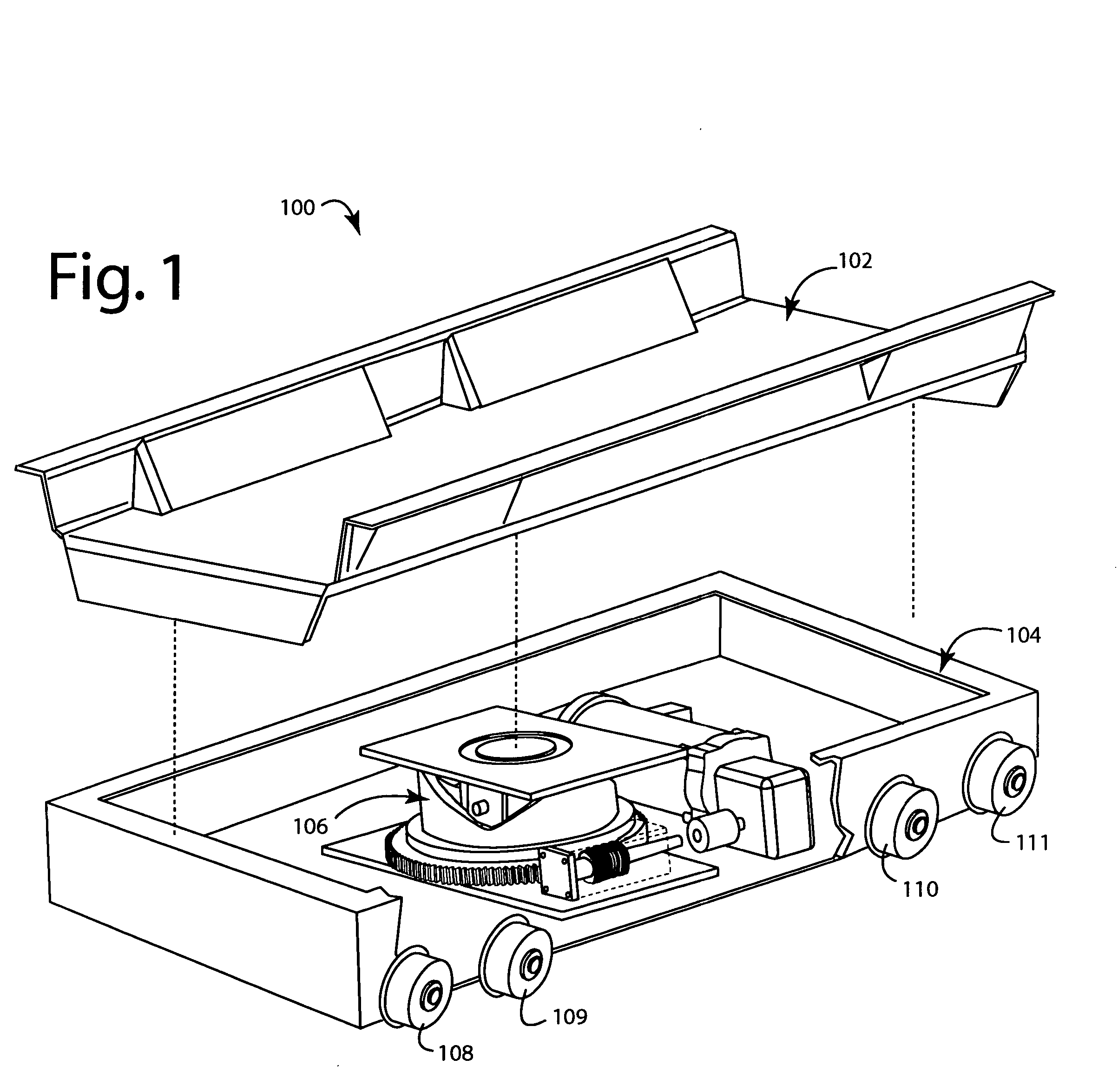
[0019]FIG. 1 illustrates a warehouse system row cart embodiment of the present invention, referred to herein by the reference numeral 100. The row cart 100 comprises a top tray 102 mounted to a rail car 104. A lifter 106 is mounted inside the rail car 104 and can smoothly lift the top tray 102 as much as a few inches higher. A set of rail wheels 108-111 is shown and a similar set is out of view on the opposite side.

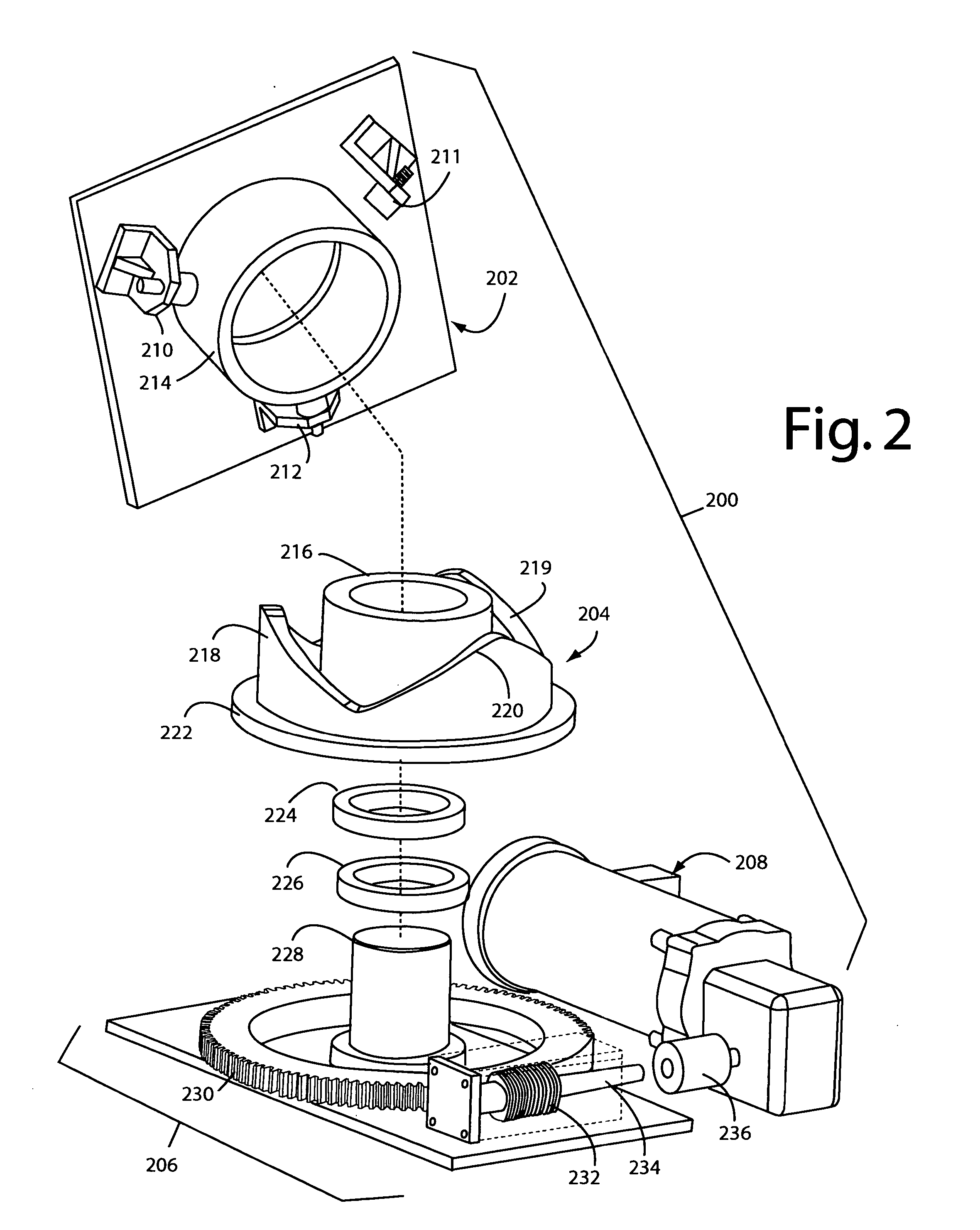
[0020]FIG. 2 illustrates a lifter embodiment of the present invention, referred to herein by the reference numeral 200. The lifter 200 comprises an elevator plate 202 that rides on a triple-lobe cam 204. Such are operated by a transmission 206 driven by a stepping motor 208. Four lobe configurations are possible, but the lobe ramping angles become so high that a great deal of torque is required to be delivered by motor 208. The torque that is required with three lobes is made practical by the high gear ratios of ring and worm gear transmissions.

[0021] The elevator plate...


PUM


Abstract

An automated warehouse system row cart includes a lifter that uses cams to raise and lower pallets. Three symmetrical cam lobes are cut into a hollow cylinder. Three matching cam lifters ride these lobes and are attached to an elevator plate. A stepper motor running in one direction is used to raise and lower the elevator plate by virtue of the action between the cam lobes and lifters.

Description

BACKGROUND OF THE INVENTION [0001] 1. Field of the Invention [0002] The present invention relates to automated storage and retrieval systems (AS / RS), and more particularly to material handling systems for storing and accessing palletized material in large multi-story automated warehouse buildings. [0003] 2. Description of Related Art [0004] Automated warehouses and automated storage and retrieval systems (AS / RS) can reduce costs, pilferage, and damage because far fewer workers are needed for otherwise similar operations. [0005] U.S. Pat. No. 6,652,213, which is incorporated herein by reference, describes an automated storage module system. Elevators operate within exterior fixed elevator shafts amongst many floors in multi-story automated warehouse. A number of corresponding aisleways at each level of the warehouse each connect to the elevators on every level. A number of rows on each level are orthogonal to each aisleway, and allow palleted material on uniform-sized pallets to be w...

Claims


Application Information

Patent Timeline
IPC IPC(8): B65G1/04B65G1/06B65G1/137
CPCB65G1/0414B65G1/06B65G1/0492
Inventor MITCHELL, PAT R.TIPTON, WILLIAM R.
Owner SWISSLOG LOGISTICS
Learn More