Rotor blade with control tube

Active Publication Date: 2012-04-12
AIRBUS HELICOPTERS DEUT GMBH
View PDF3 Cites 23 Cited by
  • Summary
  • Abstract
  • Description
  • Claims
  • Application Information

AI Technical Summary

Benefits of technology

[0016]According to a further advantageous embodiment of the invention, the rotor blade and the control tube are bonded together on the bearing face between the coupling section and the tie section. In particular, the low surface loads as a result of forming the bearing face makes this simple attachment method possible, which method reduces the installation expenditure of the connection of both sections, thus reducing production costs, in particular if there is no need for a more expensive bolt connection.
[0017]Bearing faces in the shape of the generated surface of a straight circular cylinder that forms the coupling section of the rotor blade are known. According to a further advantageous embodiment of the invention, the coupling section and the tie section, when viewed in longitudinal direction of the rotor blade and thus in the direction of centrifugal force, are designed so as to conically increase in size towards the rotor blade. The coupling section of the rotor blade thus assumes the shape of an external cone, onto which an internal cone can be slid or placed in the tie section of the control tube. If a connection, irrespective as to whether it is a bolt connection or a bonded connection, between the coupling section of the rotor blade and the tie section of the control tube, were to fail, the control tube would be pushed onto the rotor blade as a result of the effect of centrifugal force. The connection is thus designed so as to be redundant, because it still remains functional even if the connection, for example of the bonding agent, were to fail.
[0018]As a result of the arrangement of the two cones, their cone areas, which represent the bearing faces between the rotor blade and the control tube, no longer extend in the direction of centrifugal force but instead at an angle to it. Consequently the shearing forces, which act as a result of the centrifugal force, in the connecting joint between the external cone on the rotor blade and the internal cone in the control tube are reduced. The connecting means, for example the bonding agent, is thus relieved and its service life is thus extended. Instead, compressive forces in a direction perpendicular to the bearing faces are activated. The conical design both of the coupling section and of the tie section thus increases the pressing force acting on the bearing surfaces, as a result of which the connection, in particular a bonding agent, is relieved and its service life is extended.
[0019]During operation the rotor blade is not only subjected to loads resulting from centrifugal force, but also to substantial bending moments resulting from flapping of the blade section. In the fiber-reinforced composite design the rotor blade can advantageously comprise spar-like and unidirectional fiber layers that extend continuously from the blade tip through the blade section right

Problems solved by technology

However, production of this rotor blade has been shown to be e

Method used


Image

  • Rotor blade with control tube
  • Rotor blade with control tube
  • Rotor blade with control tube

Examples


Embodiment Construction

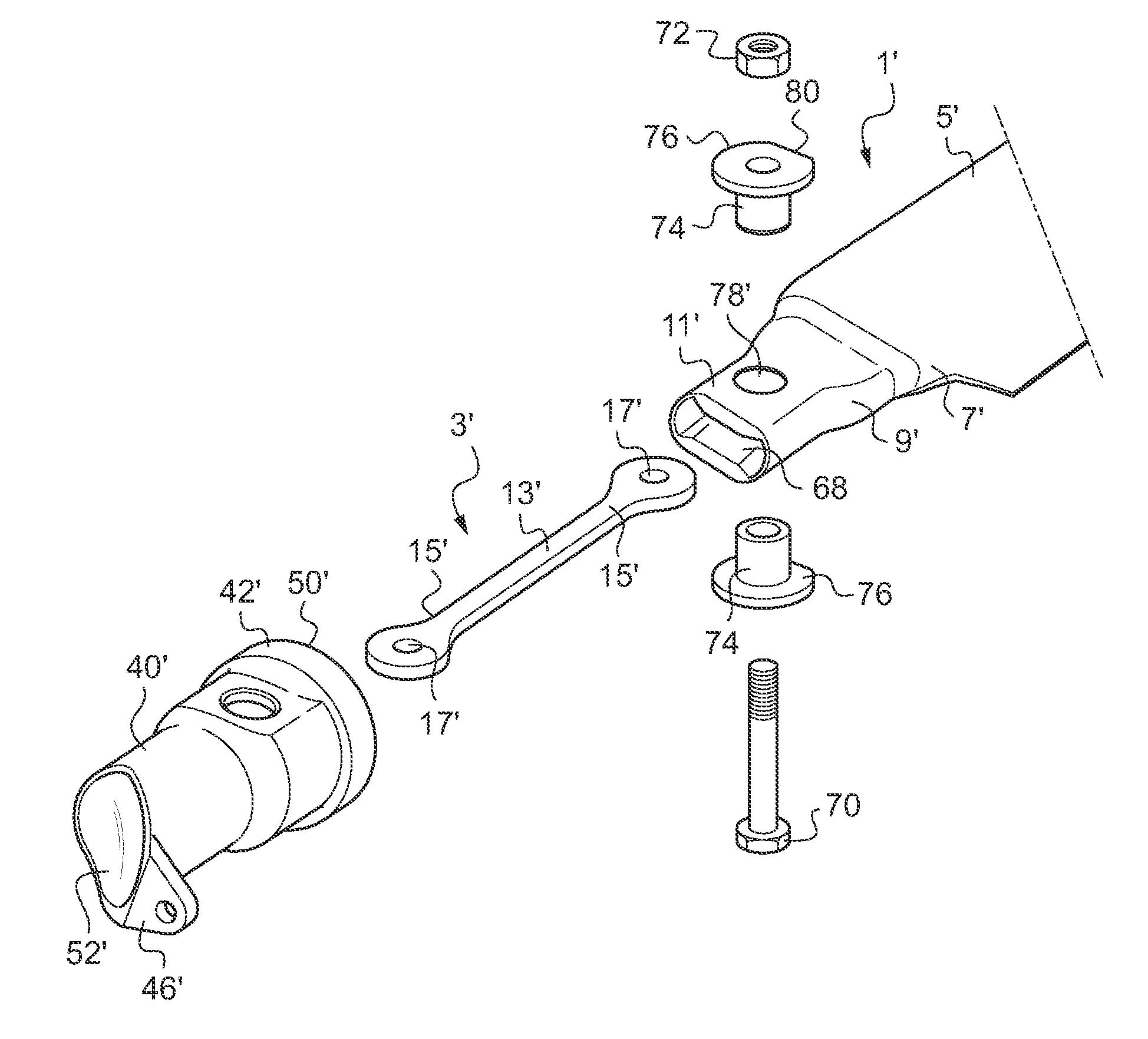
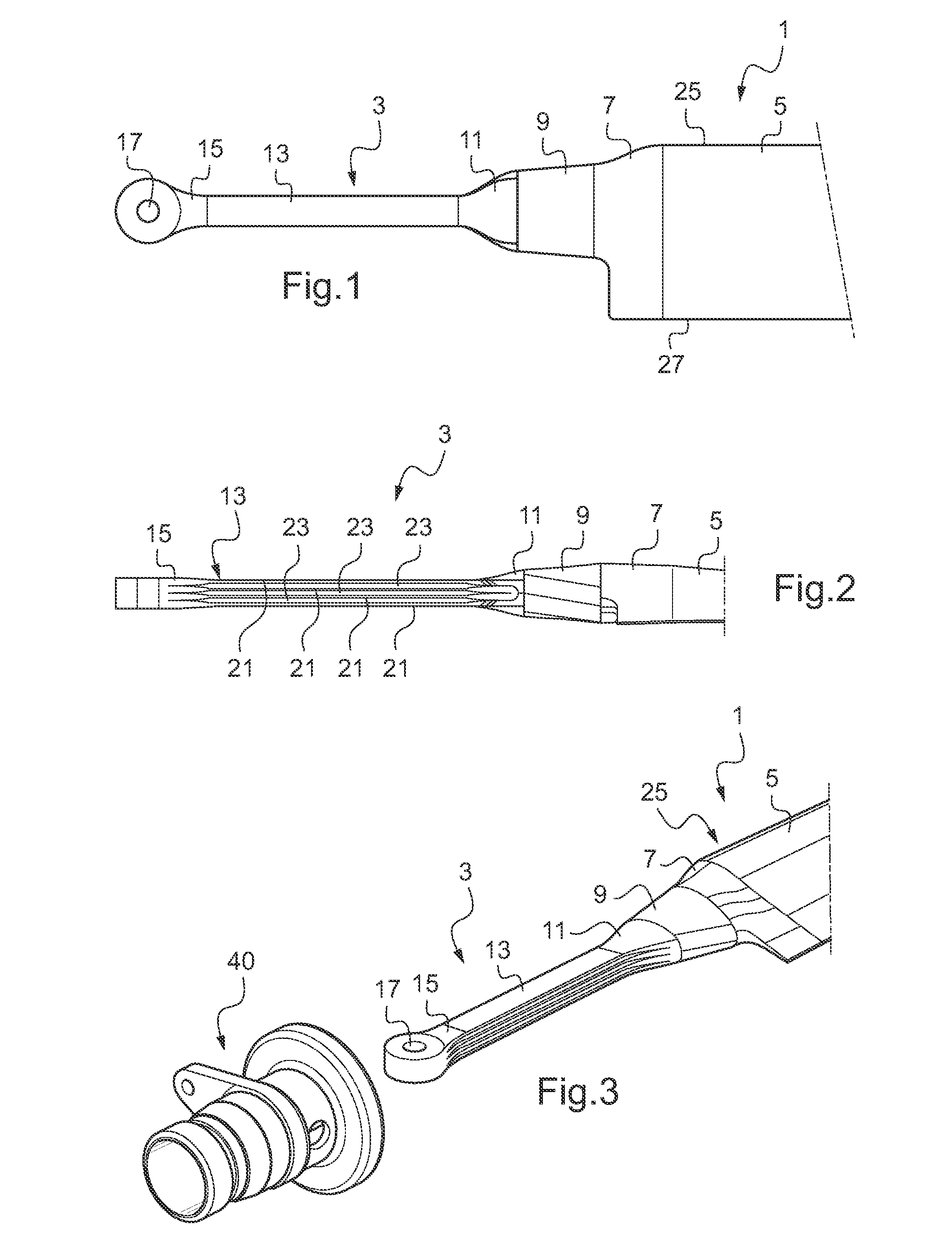
[0040]A rotor wing (only partially shown in FIG. 1) includes a rotor blade 1 and a tension-torque-transmission element 3. The tension-torque-transmission element 3 connects the rotor blade 1 to the hub of a drive device (not shown). The rotor blade 1 and the tension-torque-transmission element 3 are designed in a single piece, wherein from a blade section 5 of the rotor blade 1 on the hub side a blade transition section 7 follows on, which in turn is adjoined by a conical coupling section. It comprises a torque-transmission section 9 from which the tension-torque-transmission element 3 follows on with a blade-side connecting section 11, which in particular in top view makes a strongly conical transition to a significantly slimmer rectangular torque-transmission element 13. The latter expands to form a club-shaped connecting section 15 on the hub side, which connecting section 15 accommodates a circular connecting eye 17 that extends perpendicularly through said connecting section 15...


PUM


Abstract

A system comprising a rotor blade (1), in particular of the tail rotor of a rotary wing aircraft, in a fiber-reinforced composite design, with a blade section (5) and with a coupling section (9) for attaching the rotor blade (1) to the hub of a drive device, and comprising a separate sleeve-shaped control tube (40) with an essentially hollow-cylindrical shaft (41), with an also essentially tubular tie section (56) to tie the control tube (40) to the rotor blade (1) by sliding it onto its coupling section (9), is improved in that the coupling section (9) of the rotor blade (1) and the tie section (56) of the control tube (40) comprise a cross-sectional shape for positive-locking interconnection of the rotor blade (1) and the control tube (40).

Description

FIELD OF THE INVENTION[0001]The invention relates to a system comprising a rotor blade which a fiber-reinforced composite design, and a separate sleeve-shaped control tube, in particular for a tail rotor of a rotary wing aircraft or helicopter.BACKGROUND OF THE INVENTION[0002]Rotor wings are known, for example, from DE 693 03 152 T2. It comprises a stiff composite shell with an aerodynamic profile that extends lengthwise in accordance with the span of the rotor blade, and a tubular blade base that extends the stiff shell on the side of the rotor blade that is connected to a hub. The blade base comprises two complementary half-shells that are formed by an extension of one of two layered jackets which together form the rigid composite shell. The half-shells can also be designed so as to be separate, in other words independent of the rigid shell, and can be pushed onto a small cone on the blade, which cone is circular in cross section. By rotation of the rotor blade relative to the two...

Claims


Application Information

Patent Timeline
IPC IPC(8): B64C11/04
CPCB64C27/33B64C2027/4736B64C27/473
Inventor KUNTZE-FECHNER, GERALD
Owner AIRBUS HELICOPTERS DEUT GMBH
Why Eureka
Try Eureka