Gas phase contaminant removal with low pressure drop

Active Publication Date: 2005-06-02
CARRIER CORP
View PDF12 Cites 24 Cited by
  • Summary
  • Abstract
  • Description
  • Claims
  • Application Information

AI Technical Summary

Benefits of technology

[0009] In accordance with the present invention, it has been found that several methods for contaminant removal from a gas phase, with low pressure drop, can advantageously be incorporated into HVAC and like systems for the purpose of purif

Problems solved by technology

Unfortunately, increased energy cost results due to the need to overcome the pressure drop caused by the med

Method used


Image

  • Gas phase contaminant removal with low pressure drop
  • Gas phase contaminant removal with low pressure drop
  • Gas phase contaminant removal with low pressure drop

Examples


Example

[0026] The invention relates to a system and method for air purification, and for incorporation of an air purification mechanism into air handling systems, whereby air streams are purified with a low pressure drop, advantageously providing for improved system efficiency, reduction in required system capacity, removal of potentially harmful contaminants from the air stream improved humidity control characteristics and other benefits.

[0027] U.S. patent application Ser. Nos. 09 / 916,875, published Jan. 30, 2003 as Pub. No. US 2003 / 0021720 and Ser. No. 09 / 916,876, published Jan. 30, 2003 as Pub. No. US 2003 / 0019738, and both filed Jul. 30, 2001, disclose related systems, and are co-pending and commonly owned. These applications are specifically incorporated herein by reference.

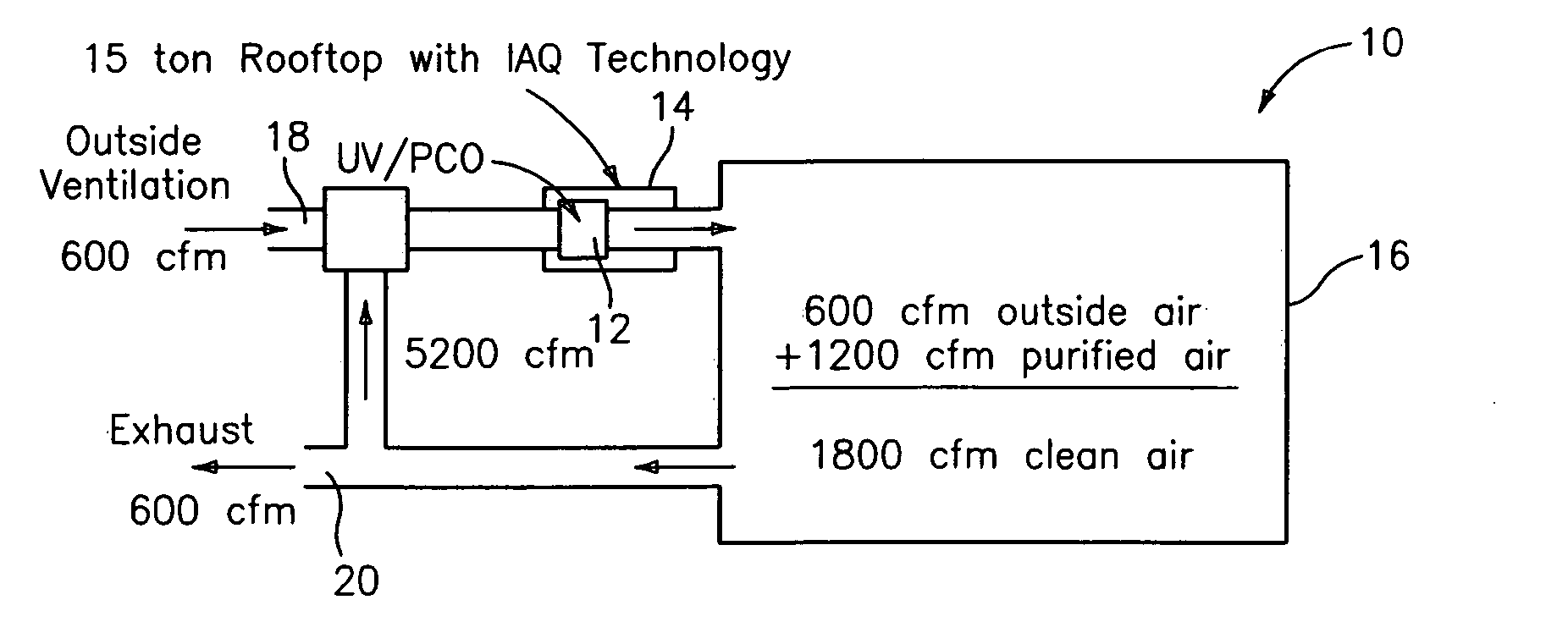
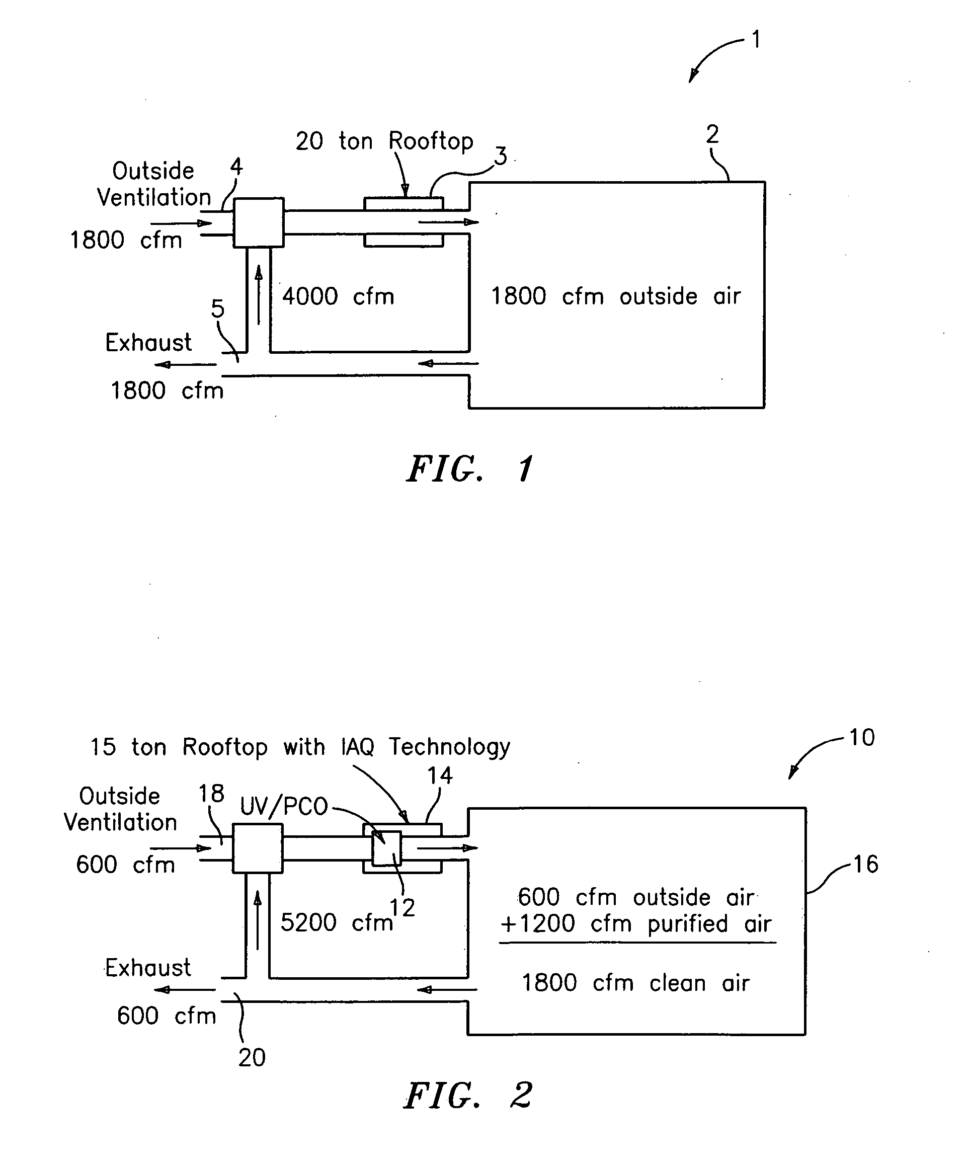
[0028] One type of air handling system to which the present application has specific application is in connection with heating, ventilation and air conditioning (HVAC) systems, one typical example of which is sch...


PUM

PropertyMeasurementUnit
Timeaaaaaaaaaa
Velocityaaaaaaaaaa
Pressureaaaaaaaaaa

Abstract

A system is disclosed which incorporates low pressure drop contaminant removal from gas phases or streams, which advantageously can be used to enhance efficiency, improve humidity characteristics, and reduce capital cost of air handing systems such as HVAC systems and the like. Placement of the low pressure drop contaminant removal mechanism for enhancing effectiveness of same is also disclosed.

Description

CROSS REFERENCE TO RELATED APPLICATION [0001] This application claims the filing date of provisional application Ser. No. 60 / 474,638, filed May 29, 2003.BACKGROUND OF THE INVENTION [0002] The invention relates to air or other gas phase handling systems and, more particularly, to removal of contaminants from gas phases. [0003] One type of air handling system to which the present invention applies is heating, ventilation and air conditioning (HVAC) systems, which are typically used to supply the heating, ventilation and cooling needs of buildings. Typically, HVAC systems are designed for four primary functions which are (1) exhaust and / or introduce outside air into the building and distribute separately or mix with recirculated air from the building, (2) cool and / or dehumidify the mixed outdoor and / or recirculated air for distribution throughout the building, (3) heat the mixed outdoor and / or recirculated air for distribution throughout the building and (4) distribute air throughout t...

Claims


Application Information

Patent Timeline
IPC IPC(8): B01D53/88B01J19/08
CPCB01D2255/802B01D53/885
Inventor DOBBS, GREGORY M.OBEE, TIMOTHYSHEEHAN, DARREN S.FREIHAUT, JAMES D.HAY, STEPHEN O.LEMCOFF, NORBERTO O.SANGIOVANNI, JOSEPH J.SAROKA, MARYHALL, ROBERT C.
Owner CARRIER CORP
Why Eureka
Try Eureka