Conductive interstitial thermal therapy device

a thermal therapy device and interstitial technology, applied in the field of body tissues treatment methods and devices, can solve the problems of inability to treat patients with such implants with rfa, inability to predict or easily control temperature, and interference with implants, so as to achieve high-predictability temperature distribution and easy control of maximum temperature

Inactive Publication Date: 2005-06-02
BIOVENTURES LLC +1
View PDF50 Cites 10 Cited by
  • Summary
  • Abstract
  • Description
  • Claims
  • Application Information

AI Technical Summary

Benefits of technology

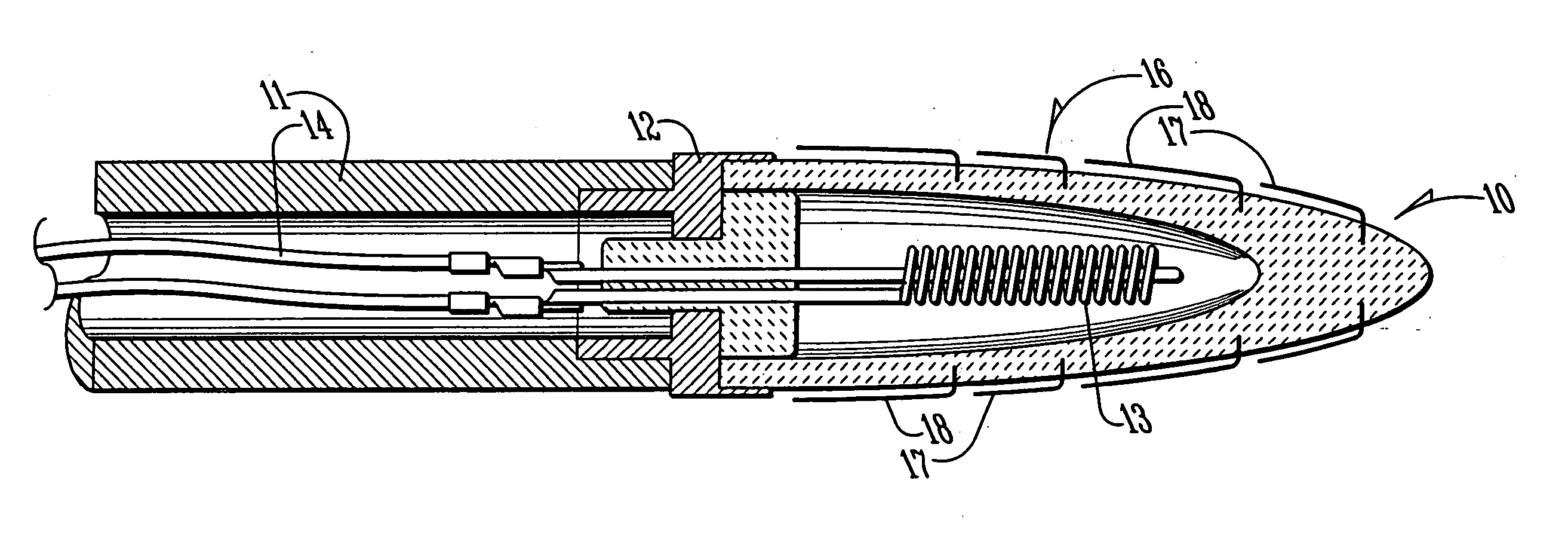
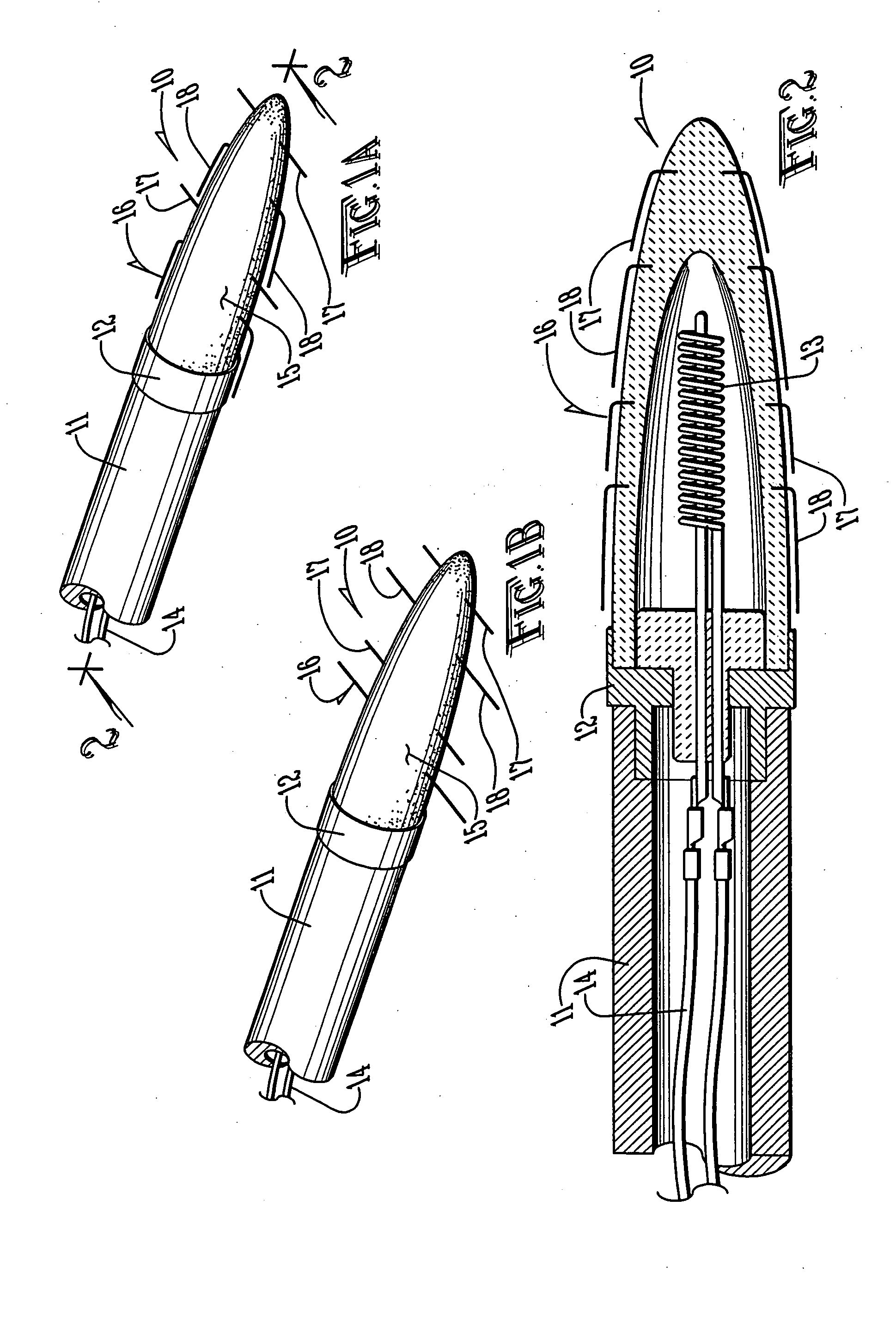
[0011] The probe comprises a thermally conductive tip containing an electrical resistance heating element. The thermally conductive tip is mounted on the end of a fiber which is separated from the tip by a heat sink to avoid thermal conduction down the fiber. The fiber contains the electrical power leads and other electrical leads connecting to monitoring devices associated with the tip. The tip is coated with a thin biocompatible coating, such as diamond-like coating, ceramic, polymers and the like, to avoid coagulated tissue sticking to the tip.
[0012] The area of tissue treated by the tip is determined by the addition of one or more thin, thermal conductive elements, which may be formed of shape memory material, such as nitinol. The shape memory elements are desirably in the form of thin wires or pins which are folded against the tip at lower temperatures and which deploy at selected higher temperatures. The shape memory elements may be deployed in multiple stages at succesively higher temperatures so that succesive layers of the tumor are exposed to specific temperatures during treatment. Coagulating the tumor in successive layers is desirable to avoid hemoraging. By selecting the number, size and placement of the shape memory elements, tumors of varying sizes and shapes may be treated in a predictable, controllable fashion.
[0013] In order to control the process, the tip may also be provided with a miniature thermocouple or the like to provide temperature feedback information to control the temperature of the tip. Through knowledge of the shape and location of the tumor obtained from computerized imaging, the design of the tip and shape memory elements, and the temperature feedback information, information can be presented to the operator showing the specific progress of the treatment of a tumor and allowing predictable control of the process.
[0018] The present invention uses thermal conduction, as opposed to radiation absorption, to heat the tumor / lesion volume. Since the thermal properties of tissue are relatively homogenous, the results can be predicted. The shape of the probe tip in the form of the deployable thermal conductive elements may be altered during treatment. The combination of shape and activation temperature can be predetermined for any specific tumor / lesion geometry. This offers the following advantages: highly predictable temperature distribution; larger areas can be effectively treated, in a controlled manner, since the heat is dissipated primarily by conduction; localized carbonization will not result in tunneling and the process is safer than LLIT or RFA; the maximum temperature in the treatment zone will never exceed the temperature at the tip of the probe, and therefore, one can easily control the maximum temperature within the tumor / lesion and adjacent tissues; temperature may be actively controlled via closed loop feedback system, where the maximum temperatures are measured during the process by placing miniature thermocouples at the end of the thermal probe.

Problems solved by technology

However, as discussed above, in the LLIT and RFA processes, the temperature cannot be predicted or easily controlled due to the varying light and RF energy absorption properties of different types of tissue.
In addition, RFA will interfere with implants (such as pacemakers) and the patient with such implants cannot be treated with RFA.

Method used


Image

  • Conductive interstitial thermal therapy device
  • Conductive interstitial thermal therapy device
  • Conductive interstitial thermal therapy device

Examples


Embodiment Construction

[0028] With reference to FIGS. 1A-10, the preferred embodiments of the present invention may be described as follows.

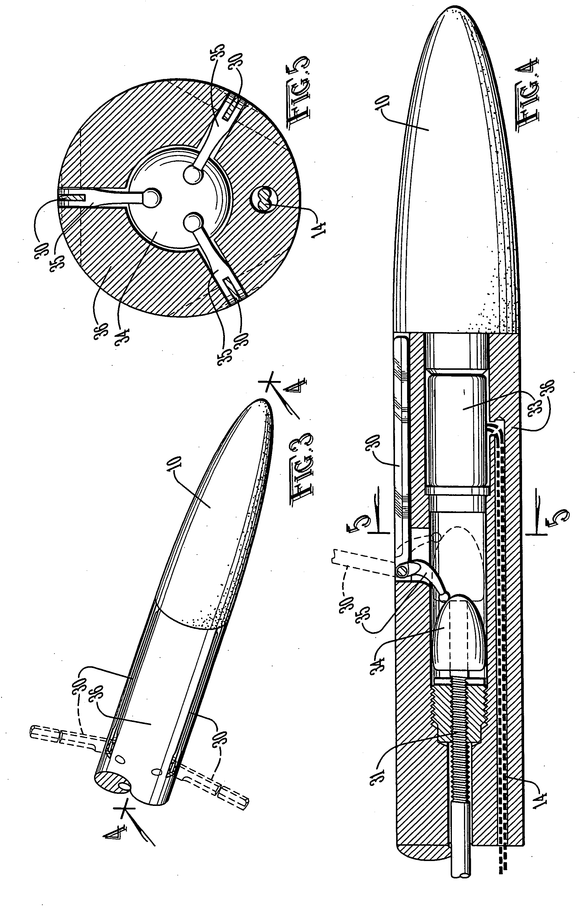
[0029] The present invention is a miniature thermal apparatus for the controlled destruction of malignant and benign tumors / lesions. As used herein, the terms tumors and lesions may be used interchangeably to indicate tissue to be thermally treated by the device and method of the present invention. The present invention comprises a tip 10 mounted onto a fiber 11 that can be inserted through a catheter that has been accurately placed within the tumor / lesion. The tumor / lesion is destroyed via heat generation originating from the specifically designed tip 10 that matches the tumor / lesion geometry. The tip 10 comprises a plurality of deployable thermal conductive elements that may be customized by the number, size and arrangement to be deployable into a geometry that matches the geometry of the tumor / lesion to be thermally treated. The temperature distribution around the...


PUM

PropertyMeasurementUnit
temperatureaaaaaaaaaa
temperaturesaaaaaaaaaa
transmissionaaaaaaaaaa

Abstract

An apparatus and method for thermally destroying tumors in which heat is generated by electrical resistance heating conducted to the target tissue. Computerized scanning is used to optimize the geometry of a thermal probe. The probe has a metal tip heated by a remote laser. The metal tip is mounted on the end of a wave guide fiber for transmitting the laser radiation to the metal tip. The tip is coated with a thin layer of biocompatible ceramic to avoid coagulated tissue sticking to the tip. The tip has one or more thin, thermally-conductive elements which deploy in stages to coagulate the tumor. The conductive elements may be thin wires or blades. On one embodiment, the conductive elements are composed of a shape memory material that is folded against the tip at lower temperatures and deploys at selected higher temperatures. In another embodiment, the conductive elements are blades that are deployed mechanically. The tip may be provided with a miniature thermocouple to provide temperature feedback information.

Description

CROSS-REFERENCE TO RELATED APPLICATIONS [0001] This application is a continuation-in-part of co-pending U.S. patent application Ser. No. 10 / 228,482 filed Aug. 27, 2002.STATEMENT REGARDING FEDERALLY SPONSORED RESEARCH OR DEVELOPMENT [0002] Not applicable. BACKGROUND OF THE INVENTION [0003] 1. Field of the Invention [0004] The present invention relates to methods and devices for treating body tissues such as tumors or lesions with thermal energy, and in particular, to such methods and devices that deploy thermally conductive elements to treat a predetermined shape of tissue. [0005] 2. Brief Description of the Related Art [0006] Within the last ten years, interstitial thermal therapy of tumors has become an accepted method for treating cancerous tumors. These minimally invasive therapeutic procedures are used to kill cancer tumors without damaging healthy tissues surrounding it. Increasing the temperature of the tumor above a threshold level of about 70-130 C will cause tumor death. In...

Claims


Application Information

Patent Timeline
Patent Type & Authority Applications(United States)
IPC IPC(8): A61B17/00A61B18/04A61B18/08A61F
CPCA61B18/082A61B2017/00867A61B2017/00084
Inventor SHAFIRSTEIN, GALFERGUSON, SCOTT L.WANER, MILTON
Owner BIOVENTURES LLC
Why Eureka
Try Eureka