Cryocooler cold-end assembly apparatus and method

a cryocooler and cold-end assembly technology, applied in lighting and heating apparatus, gas cycle refrigeration machines, refrigeration machines, etc., can solve the problems of large number of components used in current cryocoolers, laborious brazing operation, and often introduced unwanted variances in assembly linearity, so as to improve the tolerances and efficiency of cryocooler cold-end assembly, reduce the number of parts, and eliminate labor-intensive brazing and adhesion steps

Active Publication Date: 2005-06-09
SUPERCONDUCTOR TECHNOLOGIES INC
View PDF14 Cites 17 Cited by
  • Summary
  • Abstract
  • Description
  • Claims
  • Application Information

AI Technical Summary

Benefits of technology

[0009] The present invention provides for an apparatus and method for improving the tolerances and efficiency of a cryocooler cold end assembly. More specifically, the part count of the assembly is reduced and the labor intensive brazing and adhering steps are eliminated. This results in an improvement in both the manufacturing time and cost of the cryocooler. The part count is reduced in two ways. First, the components forming the external sealed housing of the cryocooler are minimized. Second, the cylindrical components (e.g., displacer, cylinder bore, and piston bore) are trued to each other by machining after installation. By truing the components, some parts can be eliminated, such as the prior art displacer cylinder bore (displacer liner).
[0010] As discussed above, in the past brazing was often employed as the construction method for connecting and sealing the various components. However, the present invention preferably eliminates brazing. Further, by machining the final critical diameters of the housing, the concentricity alignment is improved. In some instances, bushings and other friction reducing components may be eliminated entirely. Other components required epoxy bonding. By eliminating the need for this type of component assembly, another source of outgassing is removed. In some instances such as an outer design motor, outgassing components may be moved to the exterior of the external sealed housing. In this instance less contamination of the internal fluid / gas environment occurs. It will be appreciated that when the desired internal fluid / gas environment is maintained at closer to the specified levels, then the efficiency of the cryocooler is improved.
[0011] In a preferred embodiment constructed according to the principles of the present invention, the external sealed housing is constructed from a single unitary metal shell. By doing so, up to ten components of prior cryocooler cold-end assemblies are consolidated into a single part. Additionally, all brazing requirements previously necessary to secure and seal the components are eliminated. Further, due to one or more machining steps subsequent to manufacturing / forming the external sealed housing, the tolerances are improved. This allows for shrink to fit assembly of several components and also results in improved straight-line accuracy between the piston bore and the displacer cylinder. Due to this latter improvement, the need for a displacer liner is eliminated.
[0013] A feature of the present invention is the use of a non-brazed internal heat exchanger. The preferred heat exchanger is a readily machined or extruded aluminum alloy. However, the heat exchanger may be constructed of any material exhibiting good conduction properties. The prior art use of brazed fins introduced time intensive assembly processes and necessitated increased tolerances. The machined or extruded heat exchanger provides improved yield, thermal management, and a more consistent part.
[0020] While the invention will be described with respect to the preferred embodiment configurations and with respect to particular devices used therein, it will be understood that the invention is not to be construed as limited in any manner by either such configuration or components described herein. Also, while the particular shape and unitary nature of the sealed external housing are described herein, it will be understood that such particular shape and unitary structure is not to be construed in a limiting manner. Instead, the principles of this invention extend to minimizing the number of components to construct the sealed external housing so as to eliminate brazing and / or improve tolerances. Further, while the preferred embodiment(s) of the invention will be generally described in relation to use of the cryocooler in a cellular base station environment, it will be understood that the scope of the invention is not to be so limited. These and other variations of the invention will become apparent to those skilled in the art upon a more detailed description of the invention.

Problems solved by technology

One of the drawbacks of current cryocoolers is the use of a large number of components.
However, brazing is very labor intensive.
Further, the brazing operation often introduces unwanted variances in the linearity of the assemblies.
Another drawback of current cryocoolers is the inclusion of various components into the interior of the cryocooler.
By introducing unwanted gasses into the internal sealed environment, gassing often lowers the efficiency of the cryocooler.

Method used


Image

  • Cryocooler cold-end assembly apparatus and method
  • Cryocooler cold-end assembly apparatus and method
  • Cryocooler cold-end assembly apparatus and method

Examples


Embodiment Construction

.

[0021] The advantages and features, which characterize the invention, are pointed out with particularity in the claims annexed hereto and forming a part hereof. For a better understanding of the invention, however, reference should be had to the drawings which form a part hereof and to the accompanying descriptive matter, in which there is illustrated and described a preferred embodiment of the invention.

BRIEF DESCRIPTION OF THE DRAWINGS

[0022] Referring to the drawings, wherein like numerals represent like parts throughout the several views:

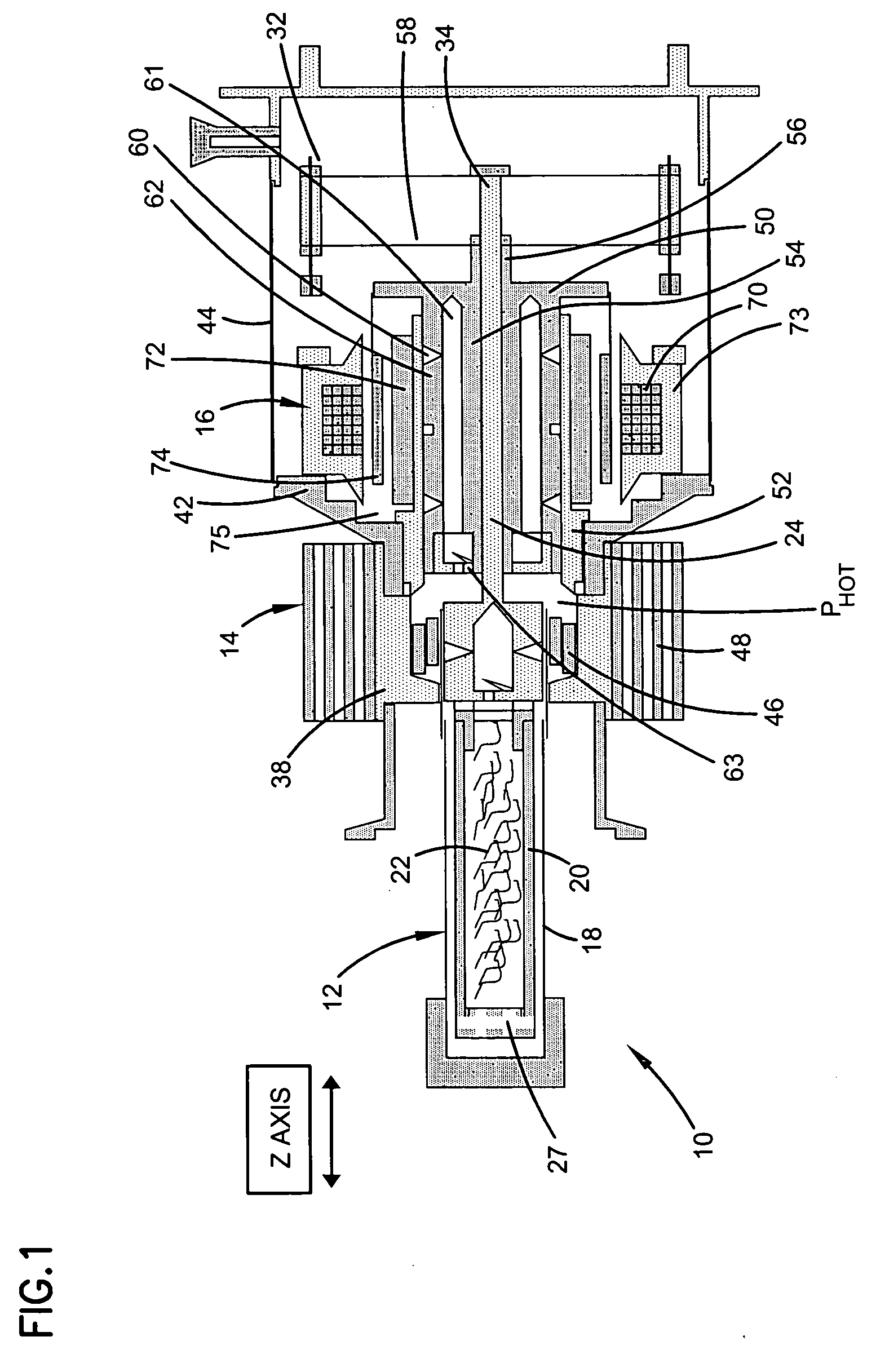
[0023]FIG. 1 is a cross sectional illustration of a prior art cold end assembly.

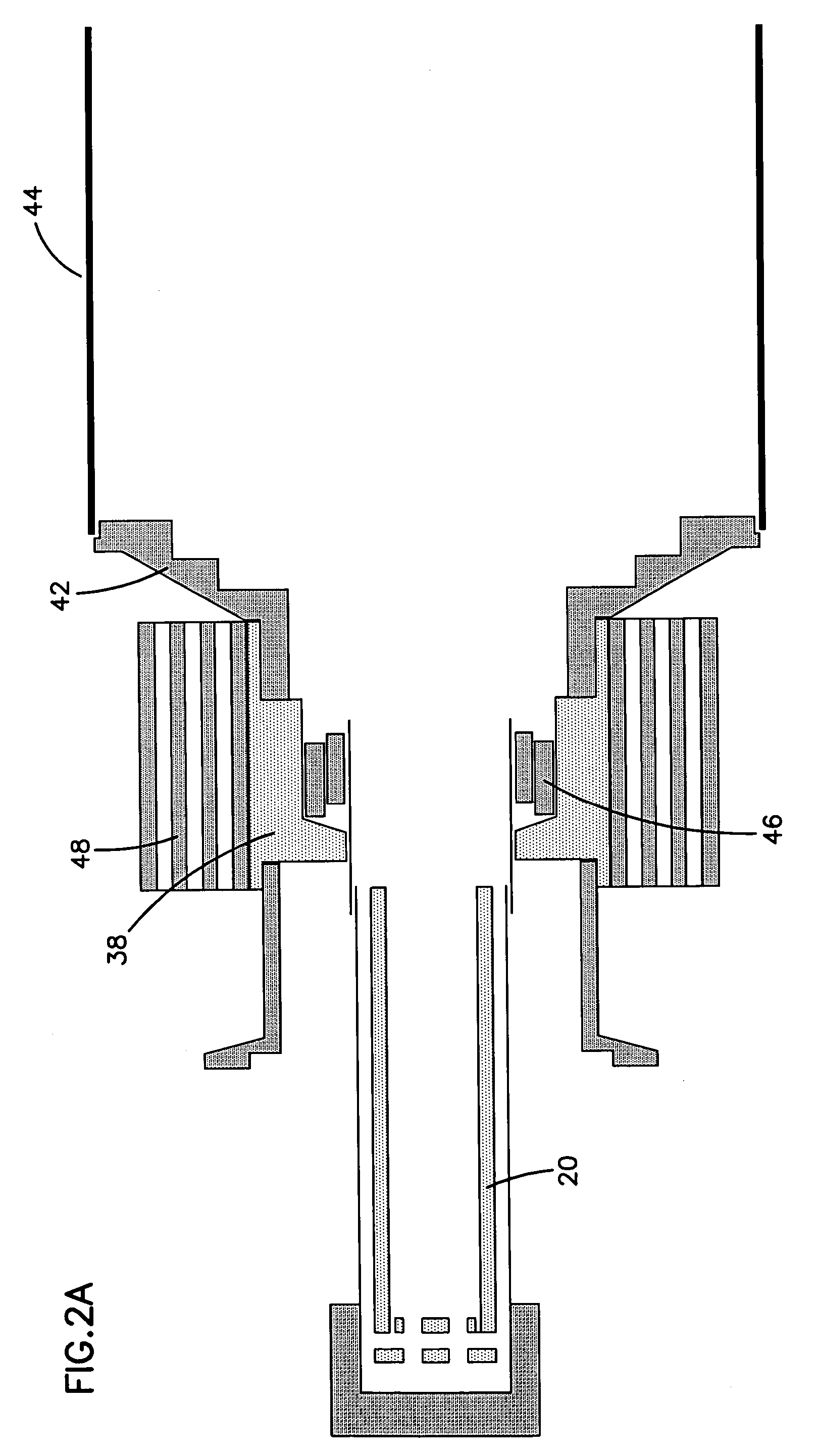
[0024]FIG. 2a is a cross sectional illustration of the external components of the cold end assembly of FIG. 1.

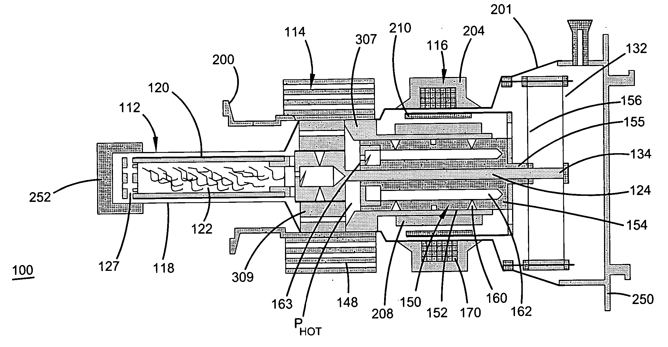
[0025]FIG. 2b is a cross sectional illustration of the various components of the cold end assembly of FIG. 1 that are replaced by components in an embodiment of the present invention constructed in accordance with the principles of the present invention. ...


PUM


Abstract

A cryocooler cold end assembly is disclosed. The assembly includes a unitary external, outer housing. By constructing the housing from a single unitary metal shell, part count is reduced from prior art assemblies. Additionally, all brazing requirements previously necessary to secure and seal the components are eliminated. Further, due to one or more machining steps subsequent to manufacturing / forming the external sealed housing, the tolerances are improved. This allows for shrink to fit assembly of several components and also results in improved straight-line accuracy between the piston bore and the displacer cylinder. Due to this latter improvement, the need for a displacer liner is eliminated.

Description

FIELD OF THE INVENTION [0001] The present invention relates generally to cryocoolers, more particularly to a unitary cryocooler cold-end assembly housing, and still more particularly to a unitary cold-end assembly housing which eliminates / minimizes brazing and provides design flexibility to locate out-gassing components either internally or externally. BACKGROUND [0002] The market for superconductor products has been growing, especially in light of a significant expanding commercial application. More specifically, high temperature superconductor (“HTS”) devices and systems have been successfully employed in cellular communication base station filters. Such filters are designed to reduce signal interference and increase base station sensitivity. [0003] To operate in their intended manner, superconductor devices must generally be cooled to extremely low temperatures. For current HTS devices, the devices must be cooled to about seventy-seven (77) K or lower. These cryogenic temperature...

Claims


Application Information

Patent Timeline
Patent Type & Authority Applications(United States)
IPC IPC(8): F25B9/14
CPCF25B2309/001F25B9/14
Inventor O'BAID, AMR HASSANHANES, MARK
Owner SUPERCONDUCTOR TECHNOLOGIES INC
Why Eureka
Try Eureka