
Three way valve and electro-hydraulic actuator using same

Inactive Publication Date: 2005-06-09
CATERPILLAR INC
View PDF11 Cites 12 Cited by
  • Summary
  • Abstract
  • Description
  • Claims
  • Application Information

AI Technical Summary

Benefits of technology

[0005] In one aspect, a three way control valve includes a valve body with a first passage, a second passage, a third passage, a first seat and a second seat. A valve member is at least partially positioned in the valve body and movable between the first seat and the second seat. The first passage is open to the third passage across the first seat when the valve member is in contact with the second seat. One of the first passage and the third passage has a flow restriction relative to the flow area across the first seat. The second passage is open to the third passage across the second seat when the valve member is in contact with the first seat. One of the second passage and the third passage has a second flow restriction relative to a flow area across the second seat.
[0006] In another aspect, an electro-hydraulic actuator includes a three way control valve with a closed control pressure volume, with a control passage a high pressure passage fluidly connected to a source of high pressure liquid, and a low pressure passage fluidly connected to a low pressure liquid reservoir. The three way control valve includes a valve member trapped to move between a high pressure seat and a low pressure seat. A movable piston with a control hydraulic surface is exposed to fluid pressure in the control pressure volume. An electrical actuator is operably coupled to the valve member. The low pressure passage is open to the control passage across the low pressure

Problems solved by technology

These problems are further compounded by issues relating to an available space envelope for the valve, and maybe more importantly the ability to address all of these problems with a structure that allows for the valve to be mass produced with consistent behavior from one valve to another.

Method used


Image

  • Three way valve and electro-hydraulic actuator using same
  • Three way valve and electro-hydraulic actuator using same
  • Three way valve and electro-hydraulic actuator using same

Examples


Embodiment Construction

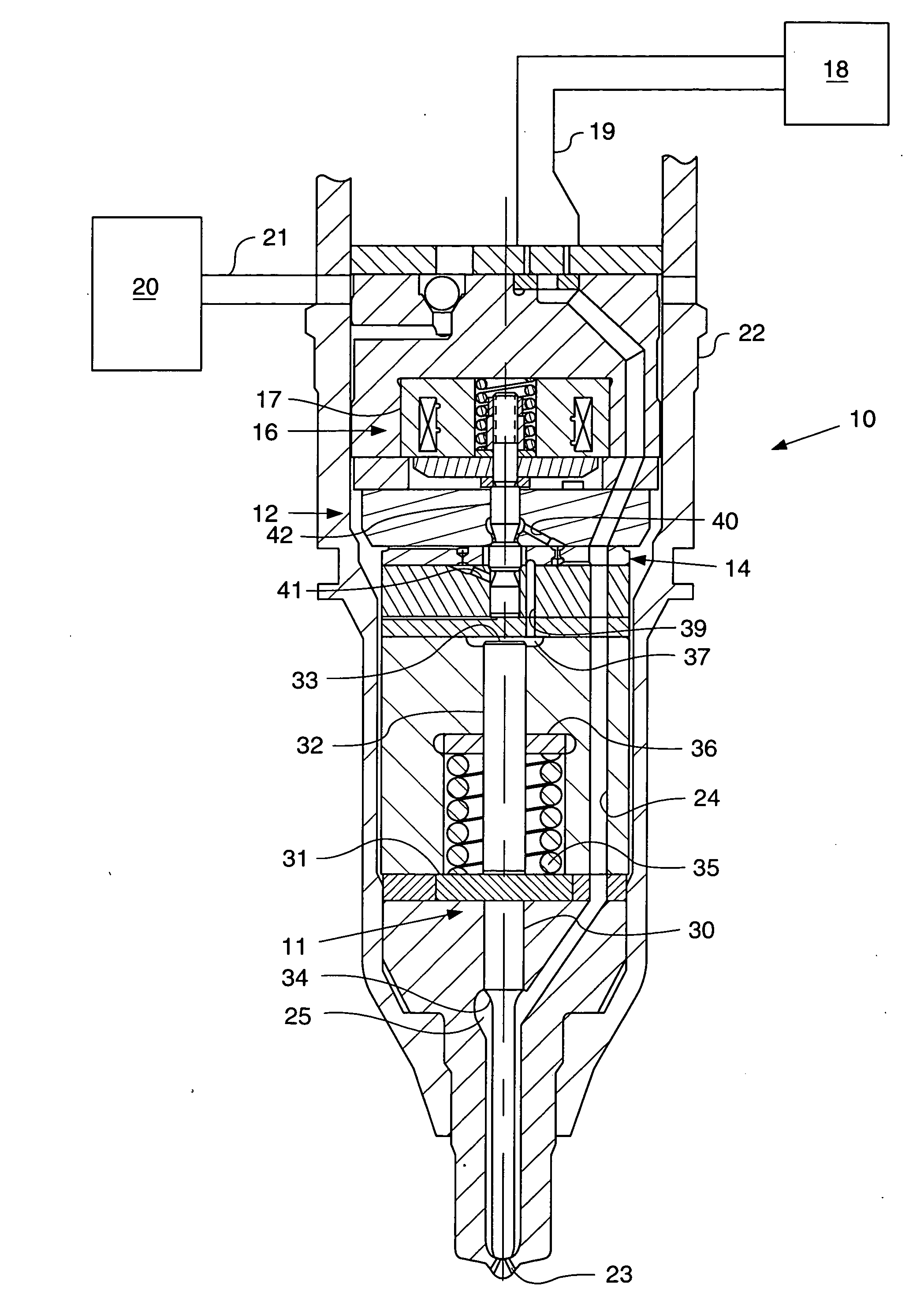
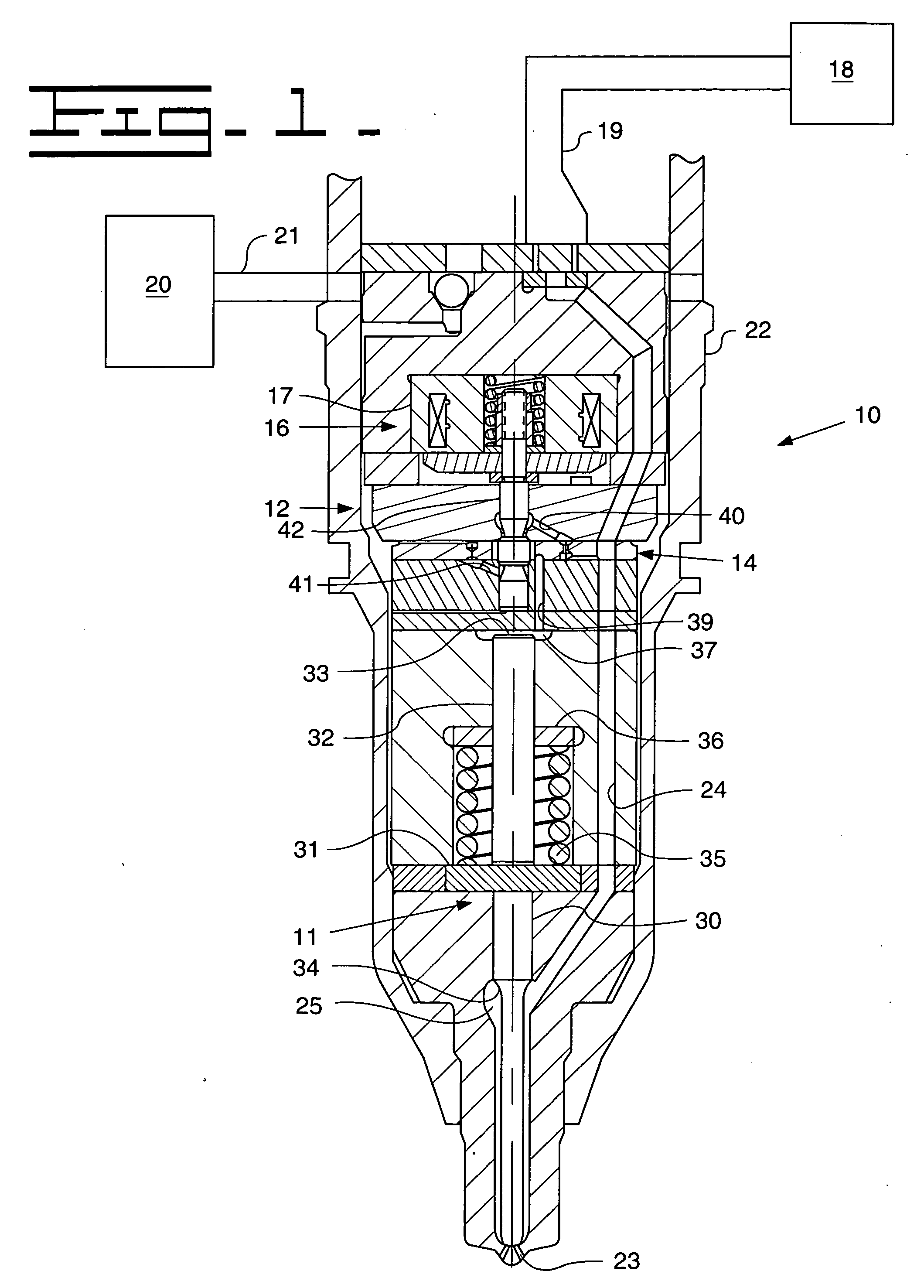
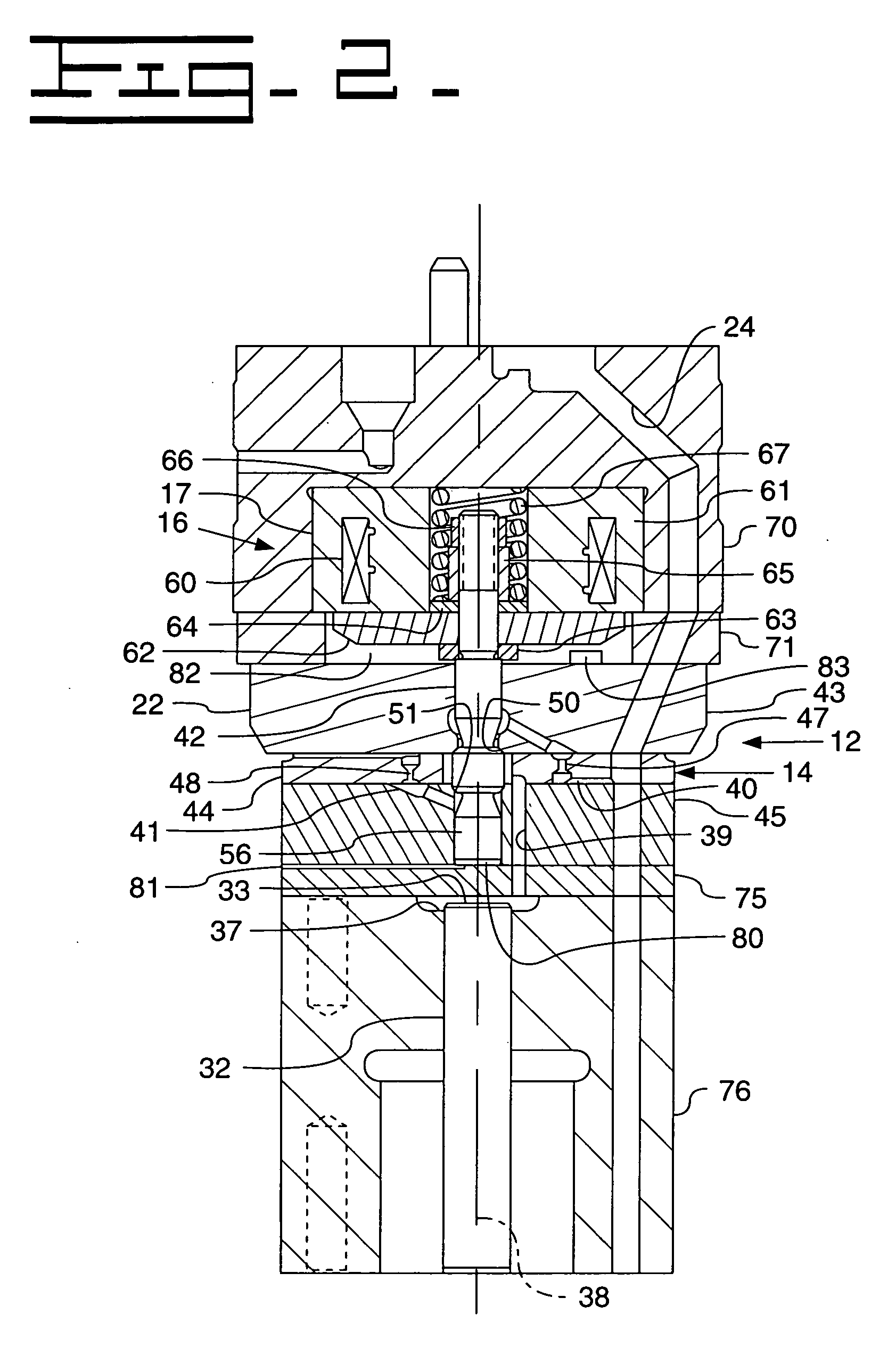
[0016] Referring to FIG. 1, a fuel injector 10 includes a direct control needle valve 11 that is operably coupled to an electro-hydraulic actuator 12. Electro-hydraulic actuator 12 includes a three way valve 14 that is operably coupled to an electrical actuator 16. Fuel injector 10 is connected to a source of high pressure fuel 18 via a fuel supply line 19, and connected to a low pressure fuel reservoir 20 via a fuel transfer passage 21. Those skilled in the art will recognize that the source of high pressure fuel 18 can come from a common rail, a fuel pressurization chamber within a unit injector or any other means known in the art for pressurizing fuel to injection levels. In addition, the injector body 22 includes at least one nozzle outlet 23.

[0017] Within fuel injector 10, fuel arriving from high pressure fuel source 18 travels through an unobstructed nozzle supply passage 24 to arrive at a nozzle chamber 25, which is shown blocked from fluid communication with nozzle outlet 2...


PUM


Abstract

The present invention relates to high speed control valves which are especially applicable for use in fuel injection systems. Producing a valve with a quick response time within acceptable packaging constraints and with a structure that allows the valve to be mass produced with consistent performance between valves is extremely problematic. By moving flow restrictions within the valve away from the valve seats, flow forces on the valve member can be reduced, while possibly also permitting a reduction in the necessary travel distance of the valve member to improve response time and other performance characteristics. The valve is particularly applicable in controlling hydraulic pressure applied to the closing hydraulic surface of a direct control needle valve in a fuel injector.

Description

TECHNICAL FIELD [0001] The present invention relates generally to high speed liquid valves with a small flow volume, and more particularly to a three way control valve for use in an electro-hydraulic actuator, such as a portion of a fuel injector. BACKGROUND [0002] Electro-hydraulic actuators, such as those used in conjunction with fuel injectors having a direct control needle valve, rely upon relatively small and fast valves in order to control fuel injection characteristics. In one class of fuel injection systems, a direct control needle valve opens and closes the nozzle outlet of the fuel injector. The direct control needle valve is controlled hydraulically via a relatively high speed needle control valve that has the ability to apply either low pressure or high pressure to a closing hydraulic surface associated with the direct control needle valve. One such direct control needle valve and accompanying needle control valve is disclosed in co-owned U.S. Pat. No. 5,669,355 to Gibso...

Claims


Application Information

Patent Timeline
IPC IPC(8): F02M47/02F02M47/00F02M51/00F02M63/00F15B13/02F15B13/044F16K11/00G05D16/00
CPCF02M47/027F02M2200/28F02M63/0045Y10T137/86622
Inventor STOCKNER, ALAN R.WIEMKEN, NORVAL J.SHAFER, SCOTT F.SLINKARD, GENE R.CAVANAGH, MARK S.TIAN, YE
Owner CATERPILLAR INC
Features
  • Generate Ideas
  • Intellectual Property
  • Life Sciences
  • Materials
  • Tech Scout
  • Unparalleled Data Quality
  • Higher Quality Content
  • 60% Fewer Hallucinations
Learn More