Laser material processing system

a material processing system and laser technology, applied in metal-working equipment, welding equipment, manufacturing tools, etc., can solve the problems of limiting the detail which may be achieved, requiring large optics, requiring engraving images on workpieces, etc., to achieve high power density, reduce size and weight, and reduce the effect of size and weigh

Active Publication Date: 2005-06-09
UNIVERSAL LASER SYST
View PDF4 Cites 8 Cited by
  • Summary
  • Abstract
  • Description
  • Claims
  • Application Information

AI Technical Summary

Benefits of technology

[0011] A laser material processing system and method focuses a laser beam to a smaller spot size with a high power density using a movable beam expander to provide high resolution laser beam for engraving and / or cutting. A movable beam focusing assembly containing at least one beam expanding optical element and at least one beam focusing optical element is a part of a motion system providing a high power density focused beam within the material processing area minimizing size and weight of the laser beam positioning optics and avoiding the problems inherent in handling and positioning a larger diameter beam.

Problems solved by technology

b>. Such configurations of known laser systems generally limit the detail which may be achieved in the cut or engraved image on the workpiece 18< /
However, such an implementation presents a problem in that an expanded beam with a larger diameter requires larger and often heavier optics to direct the expanded beam along the axes and arms of the motion system.
In addition to increasing costs, such a need for larger and heavier optics has other undesirable effects on the design of the motion system, such as requiring larger clearances for the beam, as well as stronger and / or larger motors to move the larger optics and support structures of the motion system, which ultimately drives up the purchase and maintenance costs to implement the laser beam delivery system 10.

Method used


Image

  • Laser material processing system
  • Laser material processing system
  • Laser material processing system

Examples


Embodiment Construction

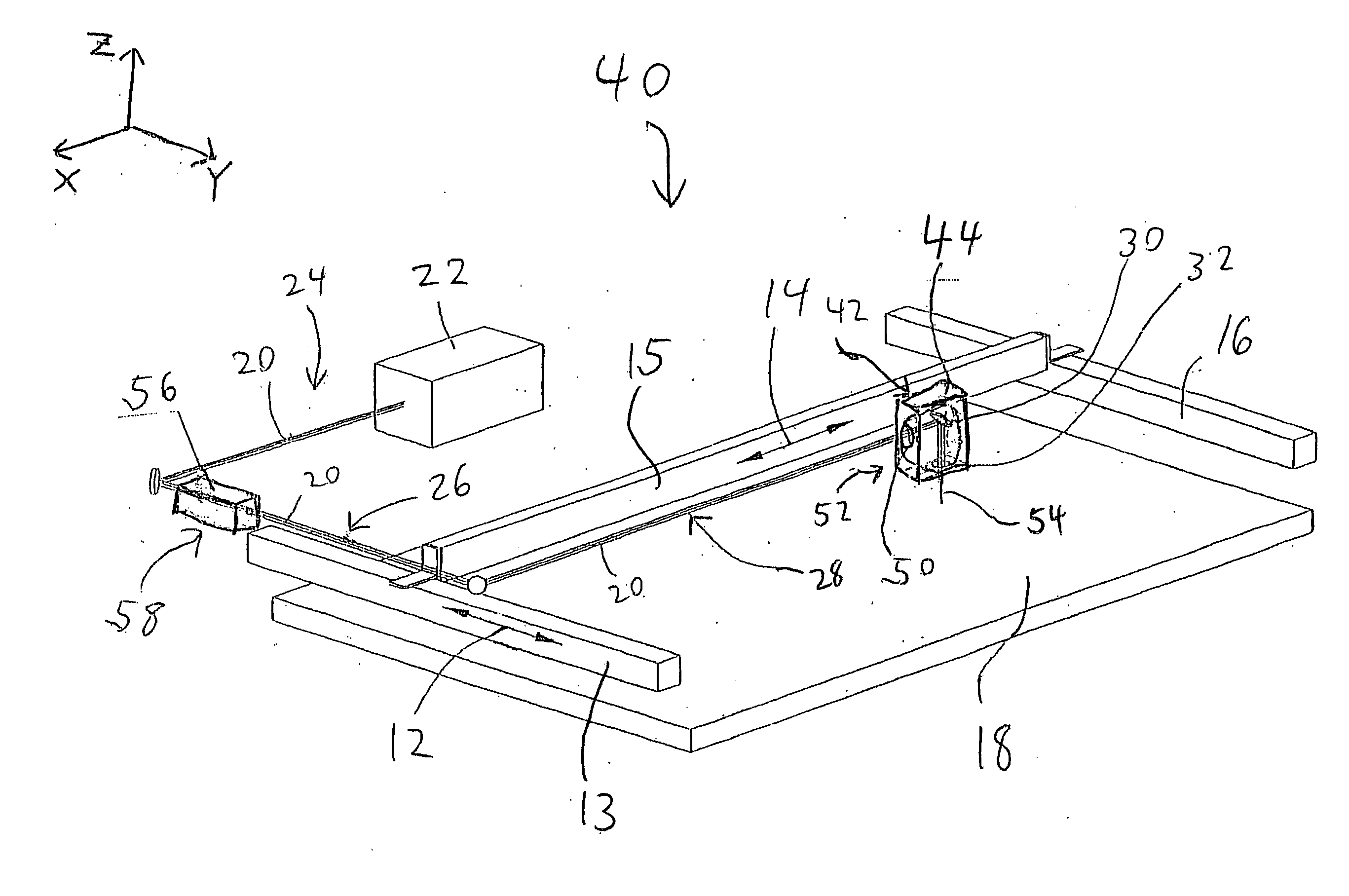
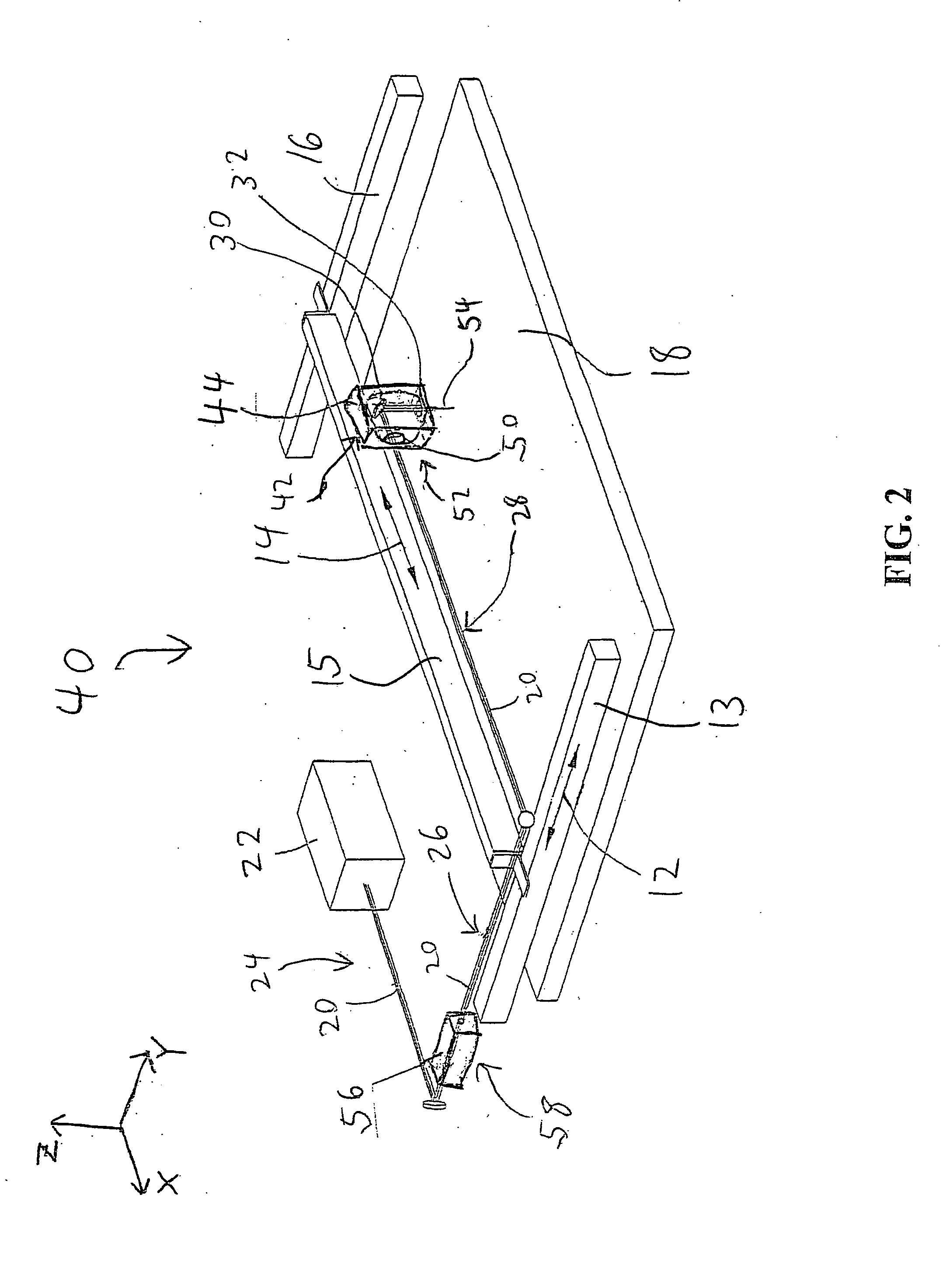
[0019] As shown in FIGS. 2-8, a laser material processing system 40 and method include a beam focusing assembly 42, shown in greater detail in FIGS. 3-6, contained in a moveable housing 44 for engraving, cutting, or etching a workpiece 18 composed of any known material capable of being modified by engraving, cutting, or etching by a laser beam. As shown in a partial cutaway view of the housing 44 in FIGS. 2-3, at least one beam expanding optical element is positioned within the housing 44 to receive a laser beam 20 and to generate therefrom a substantially divergent beam 48. The at least one beam expanding optic includes any known optical elements for expanding a laser beam.

[0020] In a preferred embodiment, the at least one beam expanding optical element includes a beam expanding lens 50. As used herein in connection with the present invention, the term “lens” is defined herein to include any known device for controlling and / or modifying the characteristics and / or direction of radi...


PUM

PropertyMeasurementUnit
sizeaaaaaaaaaa
focal lengthaaaaaaaaaa
diameteraaaaaaaaaa

Abstract

A laser material processing system and method focus a laser beam to a smaller spot size with a high power density using a movable beam expander to provide high resolution laser beam for engraving and / or cutting. A movable beam focusing assembly containing a beam expanding optics and a beam focusing optics is a part of a motion system providing a high power density focused beam within the material processing area minimizing size and weight of the laser beam positioning optics and avoiding the problems inherent in handling and positioning a larger diameter beam.

Description

CROSS-REFERENCE TO RELATED APPLICATIONS [0001] This application claims priority to U.S. provisional patent application number 60 / 527,222, filed on Dec. 4, 2003, which is incorporated herein by reference in its entirety.BACKGROUND OF THE INVENTION [0002] 1. Field of the Invention [0003] This invention relates to laser systems and in particular to a laser material processing system providing high resolution and power density of the laser beam. [0004] 2. Description of the Related Art [0005] Laser technology has numerous applications in different scientific and commercial settings. For example, laser-based imaging and fabrication, such as engraving and cutting to form artwork or other ornamental images including lettering, has become very popular, especially in the creation of artwork on various materials, such as plastics, wood, rubber and rubber-like material, paper, etc. [0006] As the state of the art of such laser technology and applications has progressed, one trend in the laser e...

Claims


Application Information

Patent Timeline
Patent Type & Authority Applications(United States)
IPC IPC(8): B23K26/06B23K26/10
CPCB23K26/0639B23K26/10B23K26/0665B23K26/0648B23K26/064
Inventor RISSER, CHRISTIAN J.GORHAM, EDWIN W.SUKHMAN, YEFIM P.
Owner UNIVERSAL LASER SYST
Why Eureka
Try Eureka