
Pipeline for the transportation of liquefied natural gas

Active Publication Date: 2005-06-09
ITP
View PDF11 Cites 10 Cited by
  • Summary
  • Abstract
  • Description
  • Claims
  • Application Information

AI Technical Summary

Benefits of technology

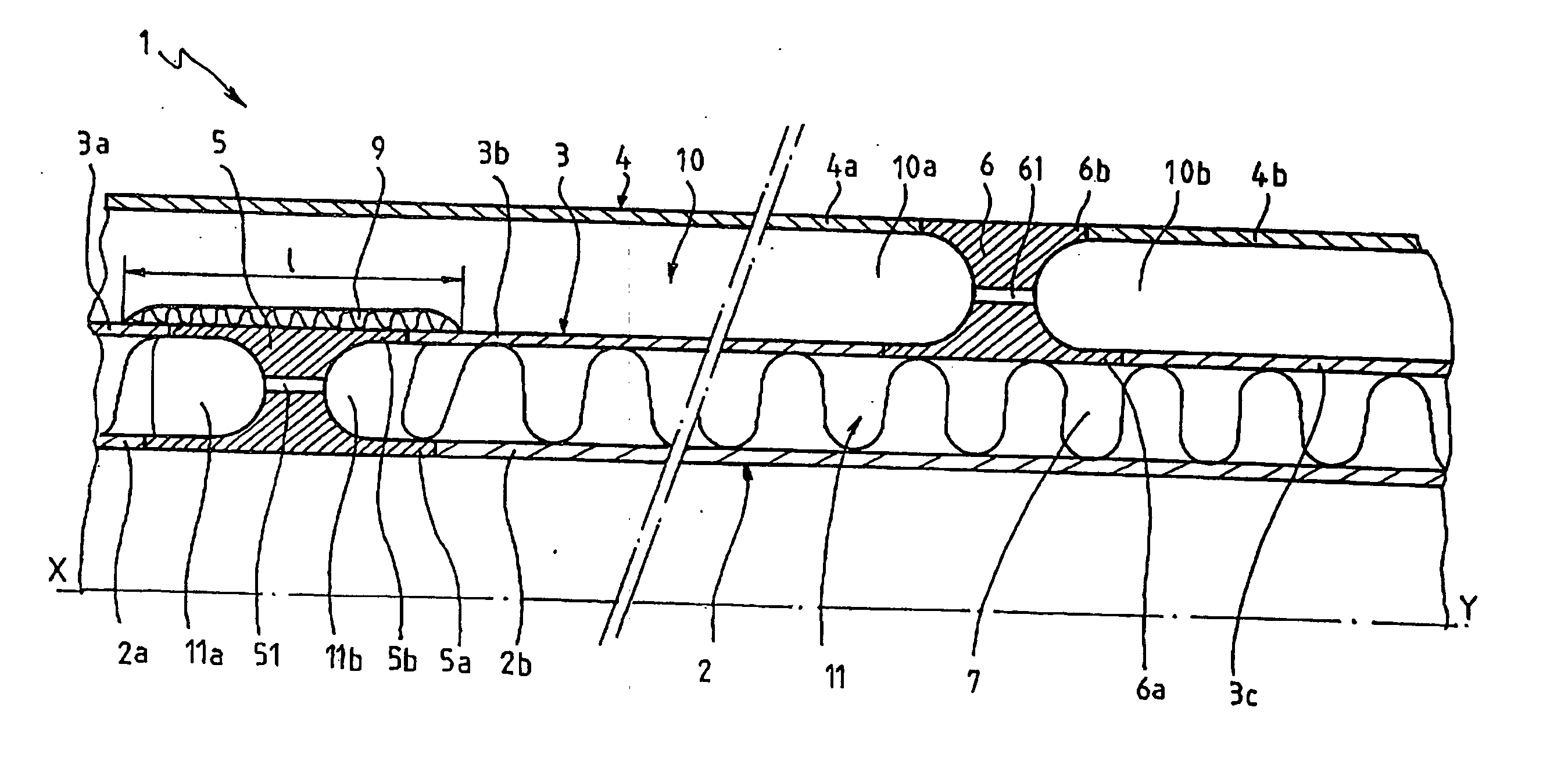
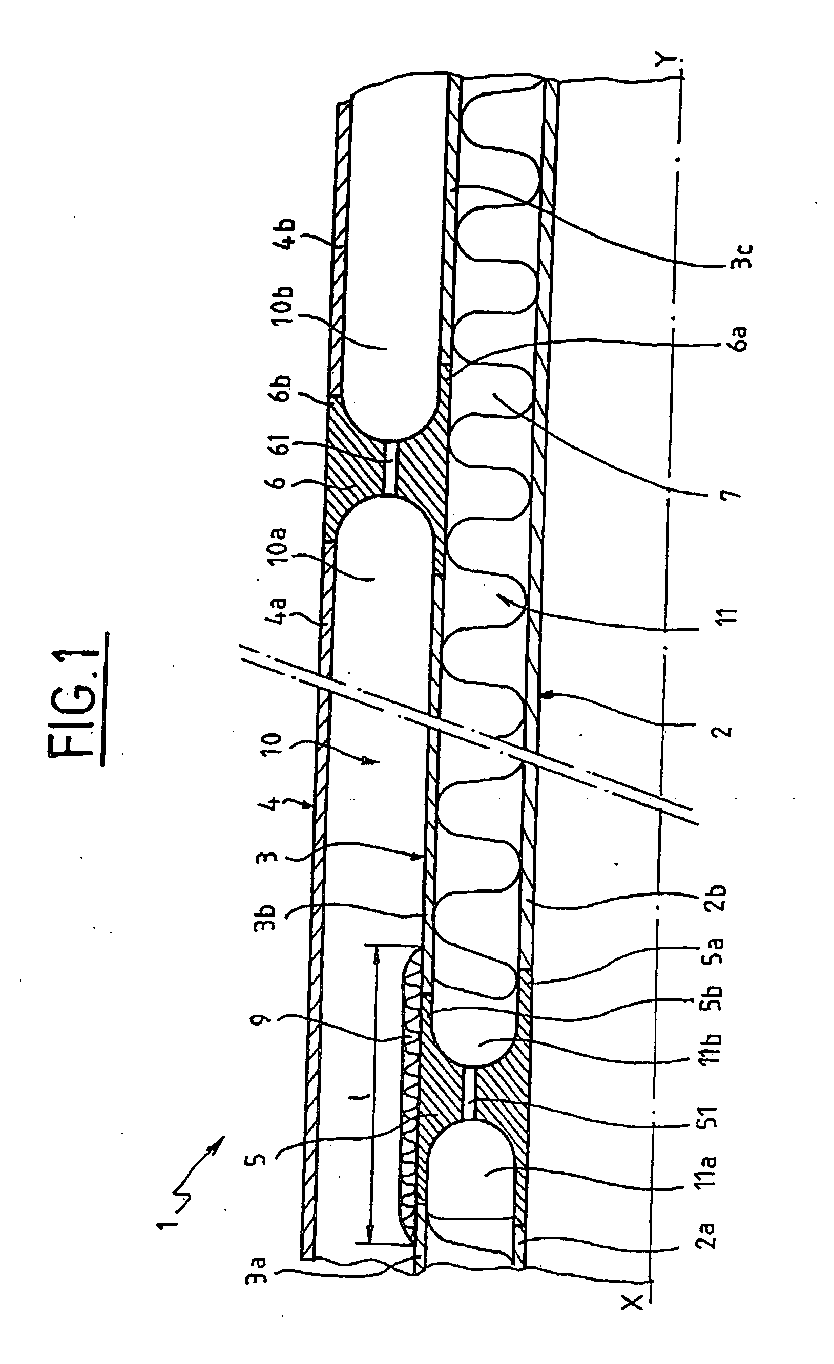
[0008] The aim of the present invention is thus to supply a pipeline for the transportation of cryogenic liquids, such as liquefied natural gas, that has efficient thermal insulation, with no thermal bridges at the ends of the pipe sections and which is extremely reliable.
[0011] the section of the middle pipe is of a sufficient length such that when assembled, in cooperation with the linking parts, it prevents the formation of a thermal bridge between the inner and outer pipes.
[0024] A first advantage of the pipeline according to the invention lies in the considerable reduction in the risk of the pipe failure.
[0025] Another advantage lies in the fact that the linking part between two adjacent pipes is able to withstand differential thermal contraction.
[0026] Yet another advantage lies in the fact that the inspection of the second annulus allows the condition of the pipeline to be verified both reliably and at little cost.

Problems solved by technology

This type of pipeline has thermal insulation properties but also suffers from drawbacks.
Indeed, the contraction of the inner pipe (by around 1 m for a pipe of a length of 4,000 m) requires the use of a steel linking part between the two pipes placed before the end bend of the straight part, such a linking part creating a thermal bridge and resulting in: a deterioration in the thermal efficiency of the assembly, a lowering in the temperature of the external pipe, thereby embrittling it and making it sensitive to impacts and concentrations of stress.
Moreover, the use of a simple external envelope cannot be considered sufficient in terms of reliability.

Method used


Image

  • Pipeline for the transportation of liquefied natural gas
  • Pipeline for the transportation of liquefied natural gas
  • Pipeline for the transportation of liquefied natural gas

Examples


Embodiment Construction

[0031] Generally speaking, the pipelines in question are used to carry a cryogenic liquid from one point to another, for example to fill or empty a ship of liquefied gas when it is far from the liquefaction plant. The pipelines are thus immersed in the sea and must rise vertically by means of a bend. The variations in length of the part of the pipeline immersed in the sea or on supports leads to variations in the position of the vertical upright part of the pipeline. These variations cause stresses in the vertical part which must be controlled. The same stresses must be controlled when the pipeline is under ground or in area.

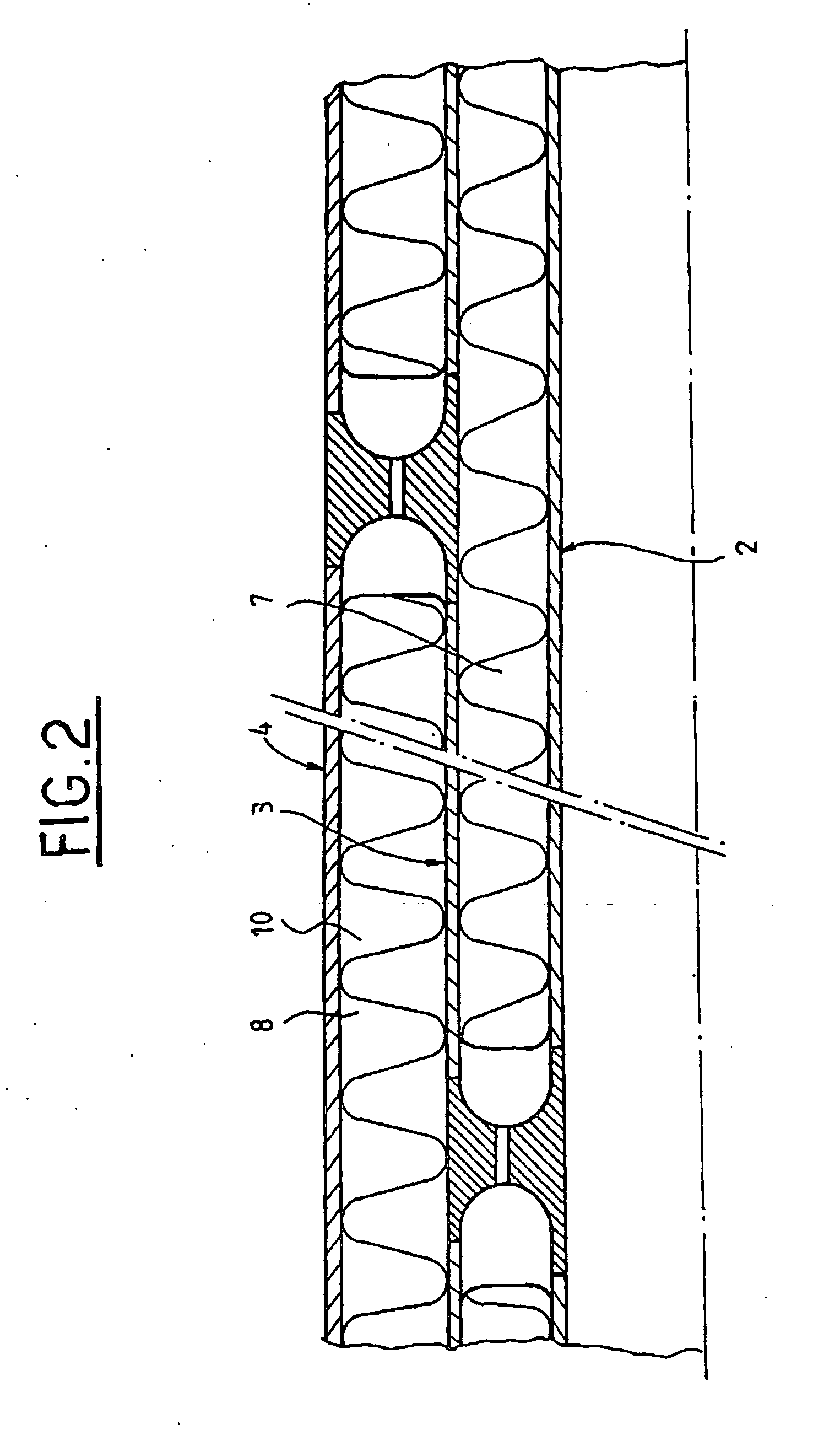
[0032]FIG. 1 partially shows a pipeline 1, sectioned along the longitudinal axis XY, intended for the transportation of a cryogenic liquid formed of three pipes: an inner pipe 2 inside which the cryogenic fluid circulates, a middle pipe 3 and an outer pipe 4. Each of these pipes is formed of sections 2a and 2b; 3a, 3b and 3c; 4a and 4b which are welded end to e...


PUM


Abstract

A pipeline for the transportation of a cryogenic liquid, thermally insulated and comprising three coaxial pipes formed of sections, one inner pipe made of a material having a low thermal dilation coefficient, a middle pipe and an outer pipe made of steel, the annulus space between the inner pipe and the middle pipe being provided with thermal insulation, wherein: the pipes are linked two by two using linking parts so as firstly to join the sections of each respective pipe and secondly to take up the loads produced by thermal contraction when the pipes change temperature. the section of the middle pipe is of a sufficient length such that when assembled, in cooperation with the linking parts, it prevents the formation of a thermal bridge between the inner and outer pipes.

Description

BACKGROUND OF THE INVENTION [0001] 1. Field of the Invention [0002] The technical scope of the present invention is that of pipelines for the transportation of very low temperature fluids, and in particular for the transportation of liquefied natural gas under ground, in area or under sea. [0003] 2. Description of the Related Art [0004] Patent FR-2748545 describes a pipeline for the transportation of liquefied natural gas comprising two coaxial pipes. This type of pipeline has thermal insulation properties but also suffers from drawbacks. Indeed, the contraction of the inner pipe (by around 1 m for a pipe of a length of 4,000 m) requires the use of a steel linking part between the two pipes placed before the end bend of the straight part, such a linking part creating a thermal bridge and resulting in: [0005] a deterioration in the thermal efficiency of the assembly, [0006] a lowering in the temperature of the external pipe, thereby embrittling it and making it sensitive to impacts a...

Claims


Application Information

Patent Timeline
IPC IPC(8): F16L9/14F16L59/14
CPCF16L59/143F16L9/18F16L59/14F16L59/22
Inventor OFFREDI, MICHAEL
Owner ITP
Learn More