Counteracting magnetic field generator for undesired axial magnetic field component of a power generator stator and associated methods

a technology of axial magnetic field and generator, which is applied in the direction of windings, magnetic circuit shape/form/construction, prevention/reduction of eddy current losses in winding heads, etc., can solve the problems of undesired eddy current heat up of stator ends, and achieve the effect of reducing an undesired axial magnetic field componen

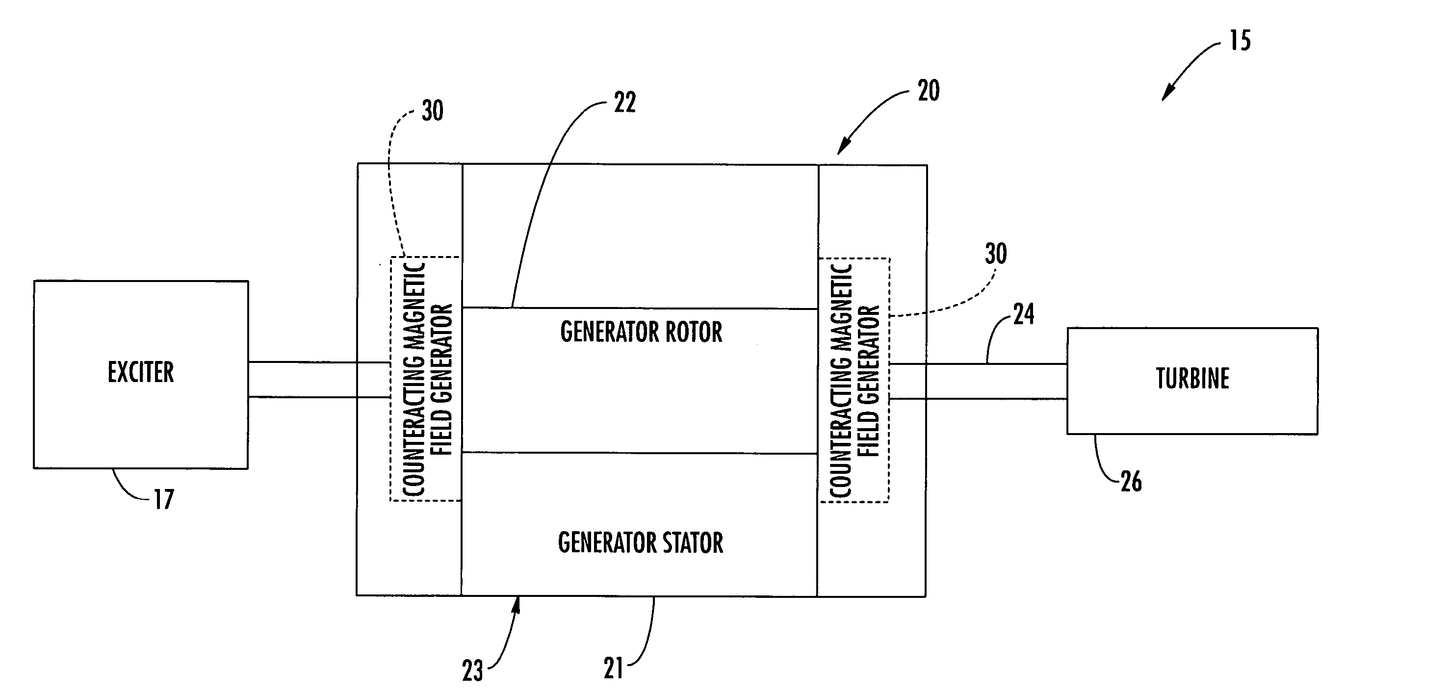
Inactive Publication Date: 2005-06-09
SIEMENS POWER GENERATION
View PDF14 Cites 12 Cited by
  • Summary
  • Abstract
  • Description
  • Claims
  • Application Information

AI Technical Summary

Benefits of technology

[0007] In view of the foregoing background, it is therefore an object of the present in...

Problems solved by technology

Rotation of the rotor within the stator may create an undesired axial magnetic field component adjacent opposing ends of the stator.
T...

Method used


Image

  • Counteracting magnetic field generator for undesired axial magnetic field component of a power generator stator and associated methods
  • Counteracting magnetic field generator for undesired axial magnetic field component of a power generator stator and associated methods
  • Counteracting magnetic field generator for undesired axial magnetic field component of a power generator stator and associated methods

Examples


first embodiment

[0027] The power generator 20′ comprises a magnetic field sensor 40′, and the power source 37′ comprises a controller 42′ for controlling the counteracting magnetic field based upon the magnetic field sensor. The power source 37′ may provide a desired phase offset for the counteracting magnetic field. The other elements of this embodiment of the power generator 20′ are similar to those of the power generator 20, are labeled with prime notation, and require no further discussion herein.

[0028] Referring now additionally to FIGS. 6-10, embodiments of the counteracting magnetic field generator 30 are now described in greater detail. A first embodiment of the first and second electrically conductive coil portions are labeled as above, i.e., 32, 34. The alternate embodiments of the first and second electrically conductive coil portions 32, 34 are labeled as increasing in numbering by 100 for each alternate embodiment. Further, a graphical illustration is provided if FIGS. 6-10 to note dir...


PUM


Abstract

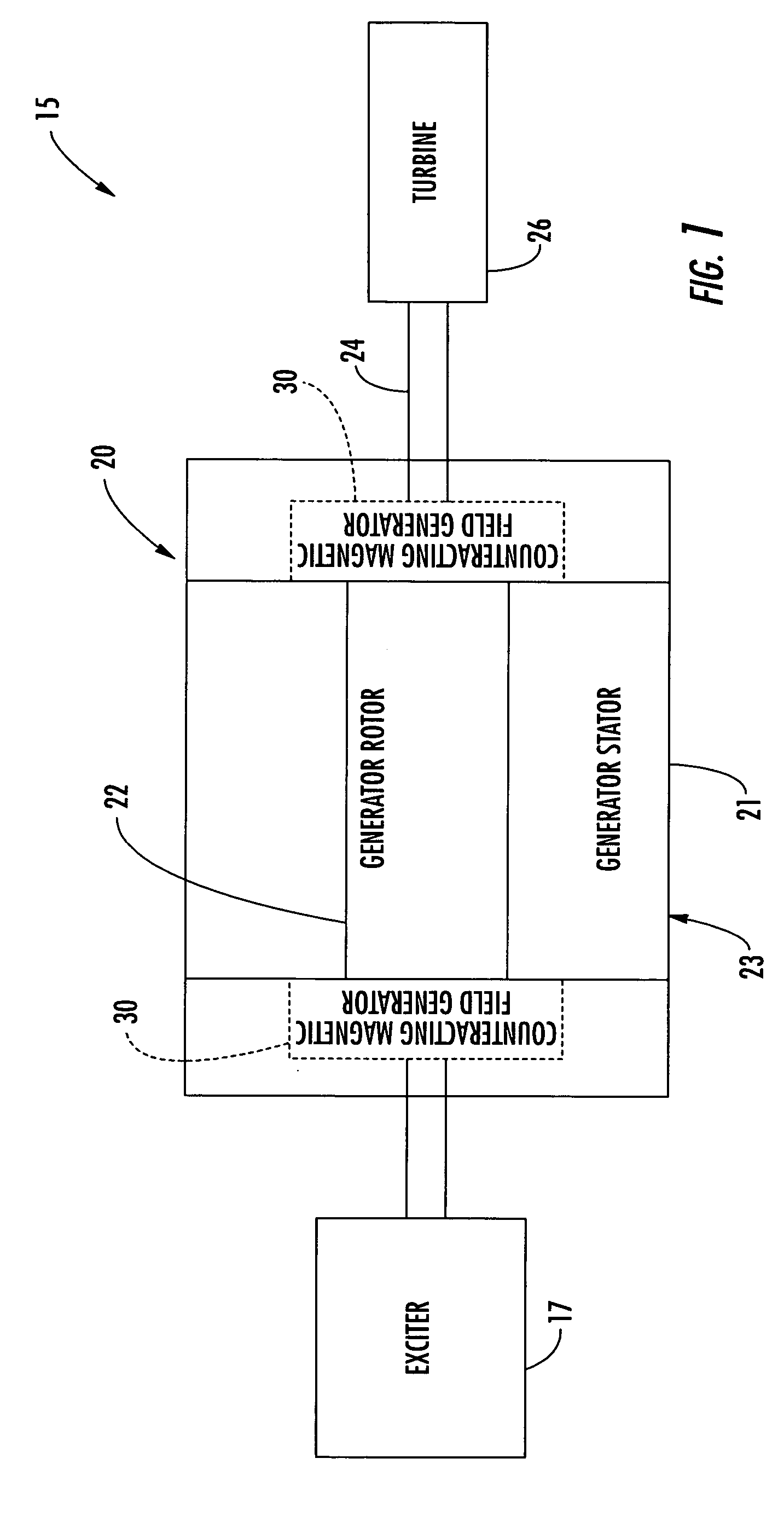
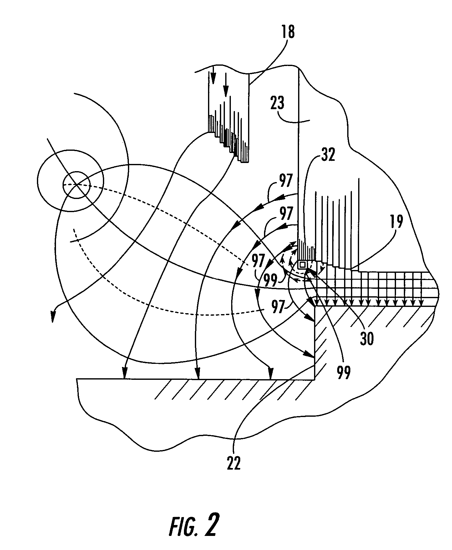
A power generator (20) includes a rotor (22), and a stator (23) surrounding the rotor and having opposing ends. The stator (23) includes a stator core (21) and a plurality of windings (28) carried by the stator core creating an undesired axial magnetic field component adjacent the opposing ends of the stator. The power generator (20) may also include at least one counteracting magnetic field generator (30) associated with at least one end of the stator (23) for generating a counteracting magnetic field for counteracting the undesired axial magnetic field component.

Description

FIELD OF THE INVENTION [0001] The present invention relates to the field of power generation and, more particularly, to a power generator and related methods. BACKGROUND OF THE INVENTION [0002] A typical power generator includes a shaft and a rotor carried by the shaft. Surrounding the generator rotor is a generator stator. A turbine, such as a gas combustion turbine, a water-driven turbine, or steam-driven turbine rotates the shaft. The generator rotor is supplied DC power typically from an exciter also driven by the shaft. As the generator rotor is turned within the generator stator, electrical power is produced and is delivered to the utility power grid. Rotation of the rotor within the stator may create an undesired axial magnetic field component adjacent opposing ends of the stator. The undesired axial magnetic field component may cause eddy currents that would undesirably heat up the ends of the stator, unless addressed. [0003] U.S. Pat. No. 6,608,419 to Shah et al. discloses ...

Claims


Application Information

Patent Timeline
IPC IPC(8): H02K11/00
CPCH02K11/0005H02K3/42H02K11/014
Inventor LEONOV, VLADIMIR
Owner SIEMENS POWER GENERATION
Why Eureka
Try Eureka