

Projection-type image display apparatus
a projection-type image and display apparatus technology, applied in the field of can solve the problems of structural complexity of the projection-type image display apparatus, increase in price and weight, and increase in the cost and weight of the apparatus, and achieve the effect of correcting the non-uniformity of luminance or color
- Summary
- Abstract
- Description
- Claims
- Application Information
AI Technical Summary
Benefits of technology
Problems solved by technology
Method used
Image

Examples
first embodiment
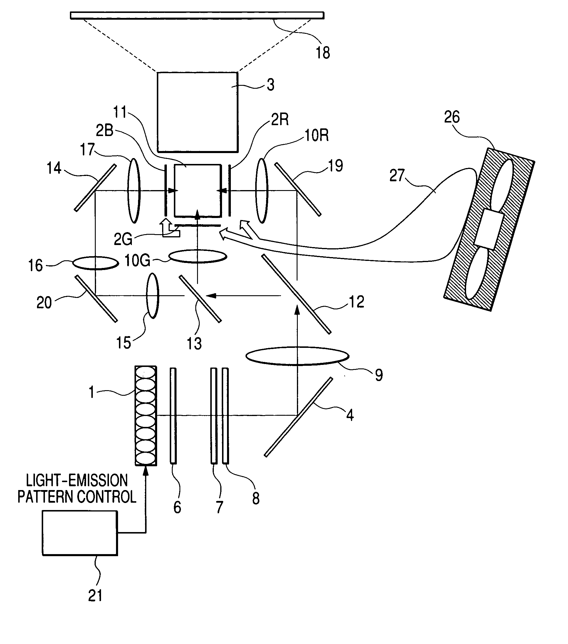
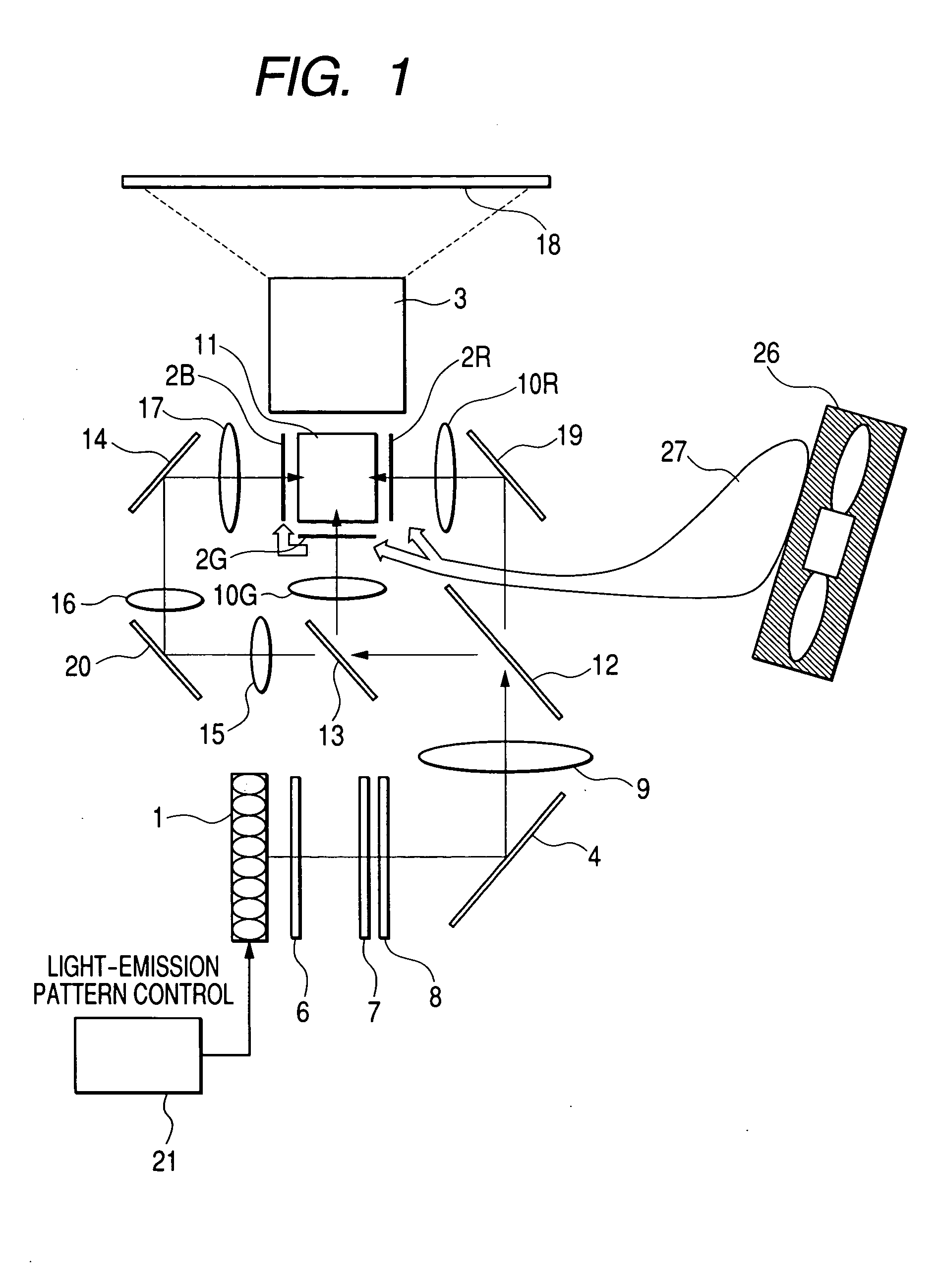
[0033]FIG. 1 shows an embodiment of the present invention. In FIG. 1, reference symbol 1 denotes a light source formed up of multiple LED elements. Also, reference symbols 2R, 2G, and 2B denote the transmissive liquid-crystal panels that are image display elements associated with the three primary colors, red (R), green (G), and blue (B), respectively. These liquid-crystal panels, by activating image signal drivers not shown, modulate, in response to image signals, luminous intensity of the beams of light emitted from the light source 1, and thus form optical images. Reference symbol 3 denotes a projection lens, reference symbol 4 a mirror, and reference symbol 6 a first lens array in integrator optics. Reference symbol 7 denotes a second lens array in the integrator optics, reference symbol 8 a polarizing conversion element for aligning in a required polarizing direction the fluxes sent from the second lens array 7, and reference-symbol 9 a focusing lens. Reference symbols 10R and ...
second embodiment
[0069] The above-described embodiment uses a mechanical selector switch to control the dimmer circuit. Next, a second embodiment, which uses electrical control, is shown in FIG. 13. In this figure, the same sections as those of FIG. 8 are each shown with the same reference numeral. In FIG. 13, a microcomputer is used instead of a mechanical selector switch.
[0070] In FIG. 13, after receiving, from an operations key 214k, an instruction for selecting either of such light-emission patterns of a light source 1 as shown in FIGS. 10A to 10C, microcomputer 214 can output a driving signal to drivers 211 (211a, 211b, 211c) on the basis of such light-emission region information as shown in FIG. 8B, the information being previously stored in a built-in memory 214m, and thus select a light-emission state of the light source 1.
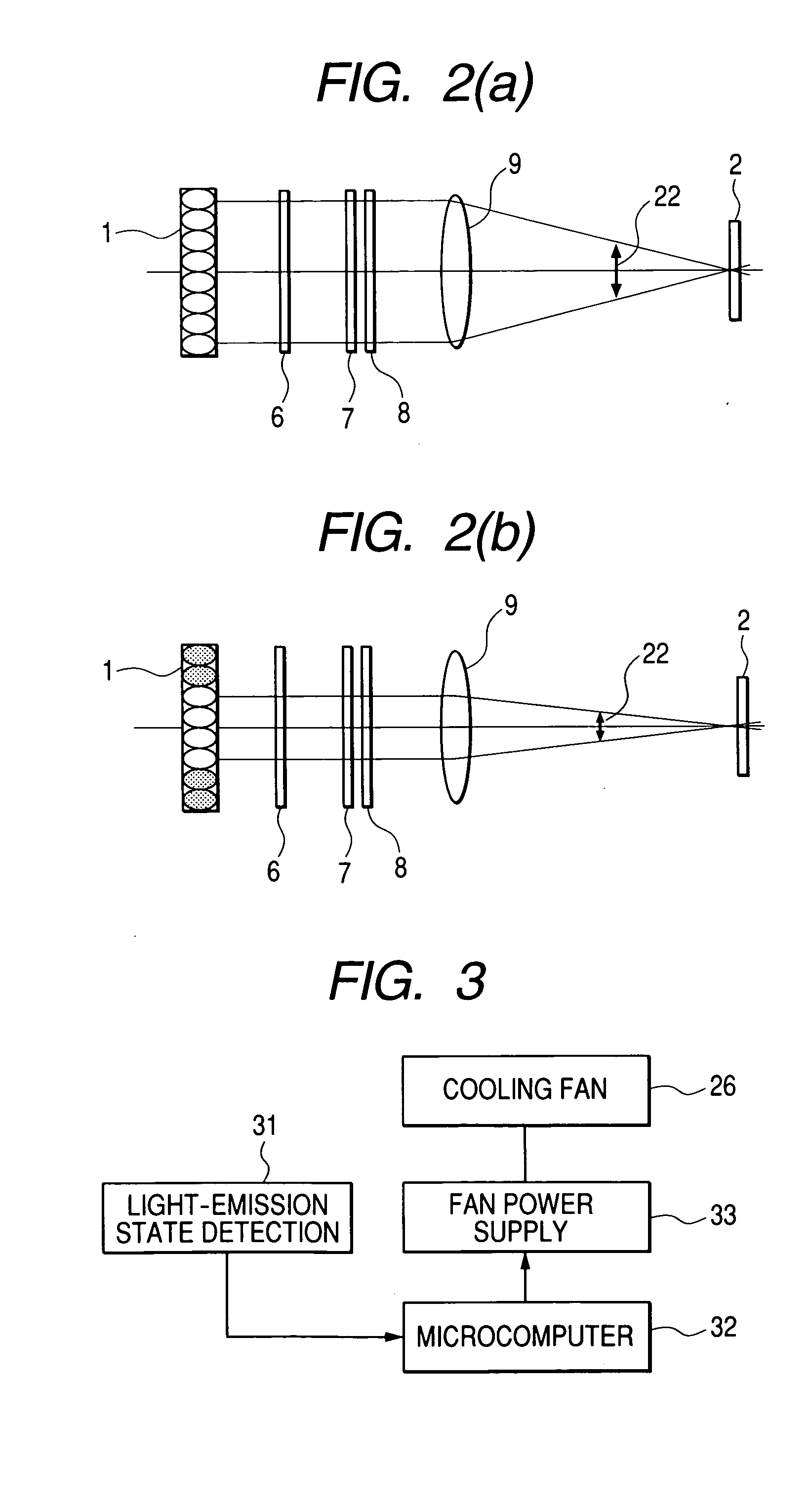
[0071] When a configuration based on microcomputer control is adopted as in the present embodiment, providing the microcomputer 32 of FIGS. 3 and 4 with the above functi...
third embodiment
[0072] An embodiment of a dimmer circuit is shown as a third embodiment in FIG. 14.
[0073] In FIG. 14, a light source 1′, unlike the light source 1 of FIG. 8B, is not wired in multiple split light-emission regions and is adapted so that all its LED elements can be independently driven. A driver 216 drives each LED element of the light source 1′ independently. For example, each LED element 5 of the light source 1′ is independently connected to the driver 216, which drives each LED so as to allow control of its turn-on / off and brightness. Such “incident-angle characteristics of contrast” as shown in FIG. 7, for example, are previously stored in the built-in memory 215m of the microcomputer 216, which, after receiving from the operations key 214k an instruction for selecting a light-emission pattern of the light source 1′, conducts on / off control of each LED element 5 of the light source 1′, based on the “incident-angle characteristics of contrast” within the memory 215m.
[0074] Constr...
PUM
 Abstract
Description
Claims
Application Information