Circuit arrangement and method for increasing the functional range of a transponder

a transponder and functional range technology, applied in the field of circuit arrangement and method for increasing the functional range of a transponder, can solve the problems of not being able to adapt the function time duration to concrete actual requirements, the function sequence itself or the result of the function sequence cannot be checked, and the conventional device of this type cannot permit any checking of the function sequence or the result of the function sequence, etc., to achieve the effect of limiting the dissipation power

Active Publication Date: 2005-06-09
ATMEL GERMANY +1
View PDF11 Cites 26 Cited by
  • Summary
  • Abstract
  • Description
  • Claims
  • Application Information

AI Technical Summary

Benefits of technology

[0028] It is another advantage of the invention that the second count makes it possible to provide a signal for terminating and/or rejecting the result of a function sequence performance when the respective performance took up more time than a predetermined number of time intervals counted by the second counter. More specifically, the function sequence is interrupted and/or rejected when the time duration determined by the second counter exceeds a predetermined time duration. As a result, unduly long function sequence durations, for example when the transponder is moved outside the permissible range, are avoided.
[0029] By providing the first counter in the valuating circuit the invention achieves the advantage that the result of a performed function sequence can be acknowledged in response to the first counter reaching a predetermined number of time intervals. More specifically, the result of a function sequence is acknowledged when the count in the first counter reaches a predetermined end value. Thus, the duration of the performance of a function sequence can be limited to the actually required duration, whereby the predetermined number of tim...

Problems solved by technology

Conventional devices of this type do not permit any checking of the function sequence itself or the result of the function sequence.
It is a particular disadvantage of conventional devices that a function duration, for example a programming duration, is fixed independently of the actual time needed for such programming.
These conventional approaches for solving the problem of achieving an increased response range have particularly the disadvantage that the measuring of the operating voltage merely is an indirect measurement of the function voltage, whereby only a breakdown of the operating voltage provides a certain reference point regarding the function voltage.
Another disadvantage of conventional devices is seen in that the control is a pure open loop control in which the function time duration is again determin...

Method used


Image

  • Circuit arrangement and method for increasing the functional range of a transponder
  • Circuit arrangement and method for increasing the functional range of a transponder
  • Circuit arrangement and method for increasing the functional range of a transponder

Examples


Embodiment Construction

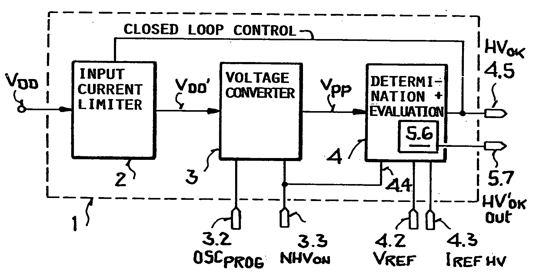
[0039] The block circuit diagram of FIG. 1 shows an overall view of the circuit arrangement 1 according to the invention. This circuit arrangement is preferably a monolithic integrated circuit for use for example in a radio frequency transponder or in a remote sensor equipped with a transponder.

[0040] The circuit arrangement 1, referred to simply as circuit 1, comprises a current limiter 2 forming the input of the circuit 1 to which an operating voltage VDD is supplied. In the present example of a transponder or remote sensor the operating voltage VDD′ is extracted from an electromagnetic field by means of a receiver component such as an antenna not shown. The electromagnetic field is transmitted by a base station. The extracted input operating voltage is rectified by a suitable rectifier such as a diode rectifier bridge not shown. Rectification is followed by a signal conditioning as is conventional.

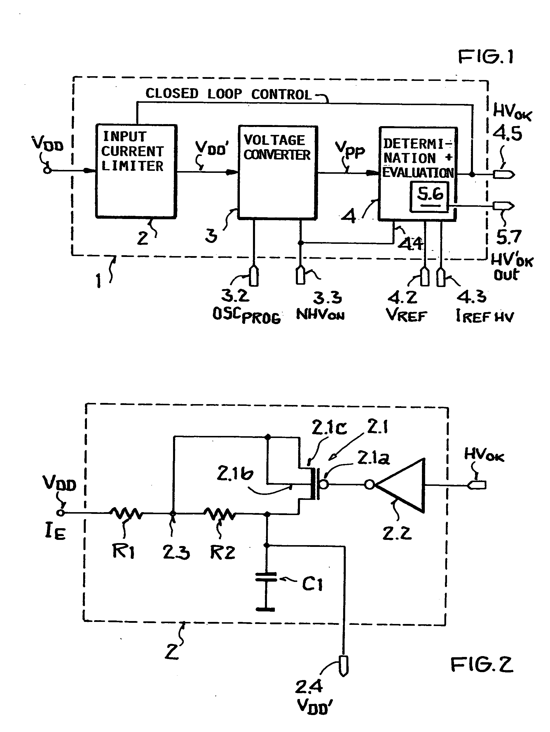
[0041] Referring to FIG. 2, the current limiter 2 provides at its output 2.4 an o...


PUM


Abstract

A transponder receives its operating energy from an external source such as a radio signal or a battery. Such transponders are used for example in a vehicle or in a remote sensor. The response range of the transponder is increased by converting the received energy into an operating voltage which in turn is used to generate a function voltage required for performing a current function sequence. The generated function voltage is checked to determine at least one characteristic of the generated function voltage. The determined function voltage characteristic, for example a voltage value directly representing the function voltage, is then used to acknowledge or reject a result of performing the function sequence. Thus, the time duration for performing any current function sequence is flexibly adapted to the current requirements of that function sequence, whereby the power consumption of the transponder is optimally reduced and the response range respectively increased.

Description

PRIORITY CLAIM [0001] This application is based on and claims the priority under 35 U.S.C. §119 of German Patent Application 103 56 259.1, filed on Dec. 3, 2003, the entire disclosure of which is incorporated herein by reference. FIELD OF THE INVENTION [0002] The invention relates to a circuit arrangement for increasing the functional range of any transmission device that derives its operating power from a source such as a battery or the energy of an electromagnetic field through which a signal is transmitted to the device such as a transponder or a remote sensor. BACKGROUND INFORMATION [0003] The present circuit arrangement and method are particularly adapted for use in a transponder or in a remote sensor that has a transponder for responding to an interrogation transmitted through an electromagnetic field. In this context the term “transponder” is intended to encompass any apparatus that receives its operating energy from a source such as an electromagnetic field. For this purpose...

Claims


Application Information

Patent Timeline
IPC IPC(8): G06K19/07G06K19/073
CPCG06K19/0701G06K19/073G06K19/0723G06K19/0715
Inventor FISCHER, MARTINFLASSNOECKER, VOLKHARDFRIEDRICH, ULRICHZIEBERTZ, DIRK
Owner ATMEL GERMANY
Why Eureka
Try Eureka