Method for supporting reflector in optical scanner, optical scanner and image formation apparatus

Inactive Publication Date: 2005-06-09
PANASONIC CORP
View PDF22 Cites 2 Cited by
  • Summary
  • Abstract
  • Description
  • Claims
  • Application Information

AI Technical Summary

Benefits of technology

[0083] According to the present invention, a reflector is supported at end portions of the reflector and also at a point which is located in the vicinity of a center portion of the reflector so as to be more toward a concave side of a reflection plane than an imaginary straight line joining respective supporting points in the end portions. Thus, even with the reflection plane curved from the long side direction of the reflector, the reflector is stably supported, so that a vibration can be suppressed.
[0084] If corresponding portions of the reflector located in the opposite side of the reflector to a side thereof in which the support points are located are pressed, the reflector can be more stably supported.
[0085] By providing a rib extending in a back side of a reflector body, the strength of the reflector can be improved. Moreover, the strength is ensured by the rib, and thus the reflector body can be formed so as to have a small thickness. Therefore, accuracy in processing the reflection plane can be improved.
[0086] If the cen

Problems solved by technology

However, it is difficult to process a glass lens into a complicated shape and thus it is difficult to form the second image formation optical system of a single glass lens.
Glass lenses are, however, of an expensive optical element.
When the second image formation optical system is formed of glass lenses, a plurality of expensive glass lenses are needed.
Therefore, it has been difficult to r

Method used


Image

  • Method for supporting reflector in optical scanner, optical scanner and image formation apparatus
  • Method for supporting reflector in optical scanner, optical scanner and image formation apparatus
  • Method for supporting reflector in optical scanner, optical scanner and image formation apparatus

Examples


Example

Embodiment 1

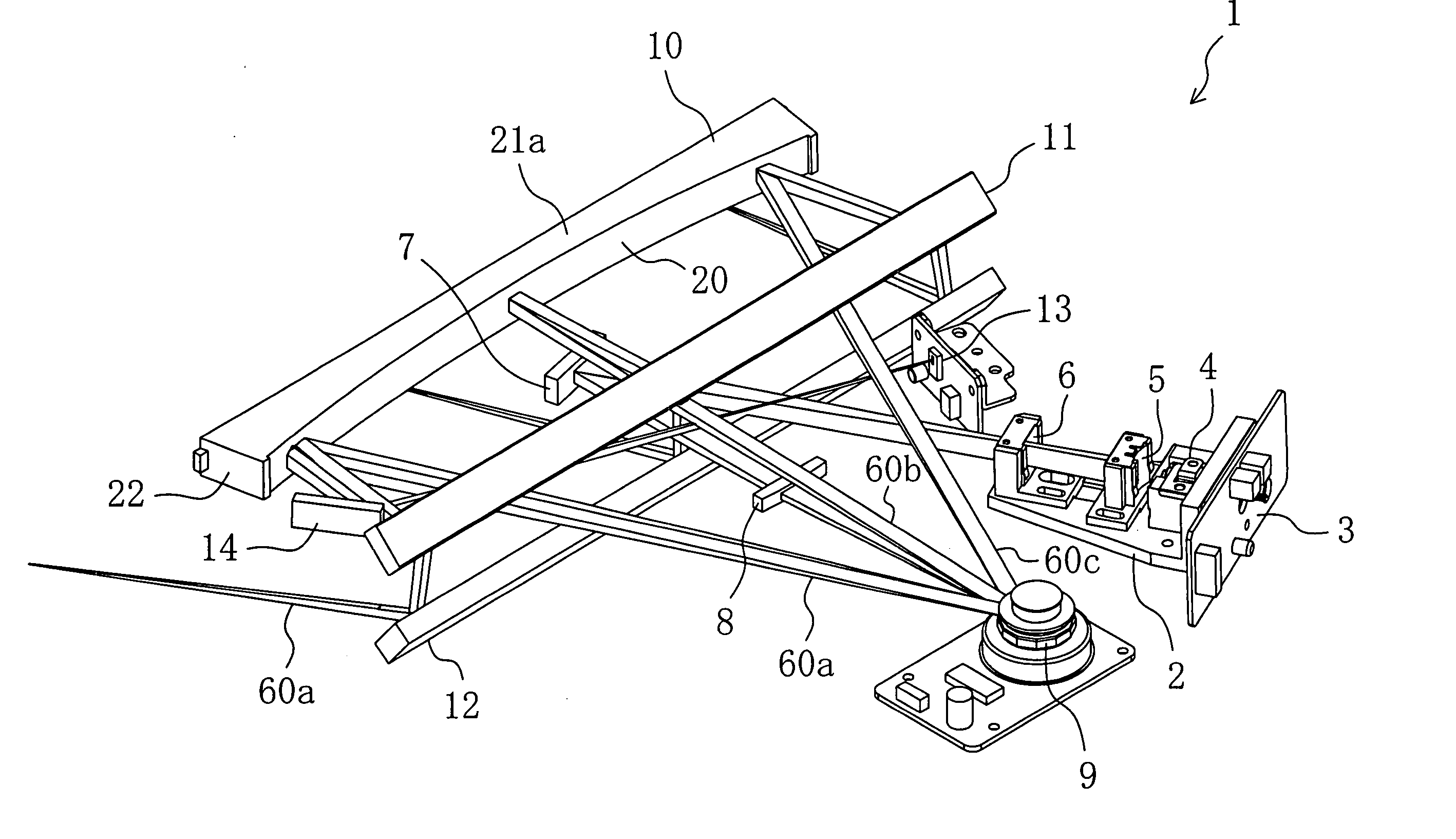
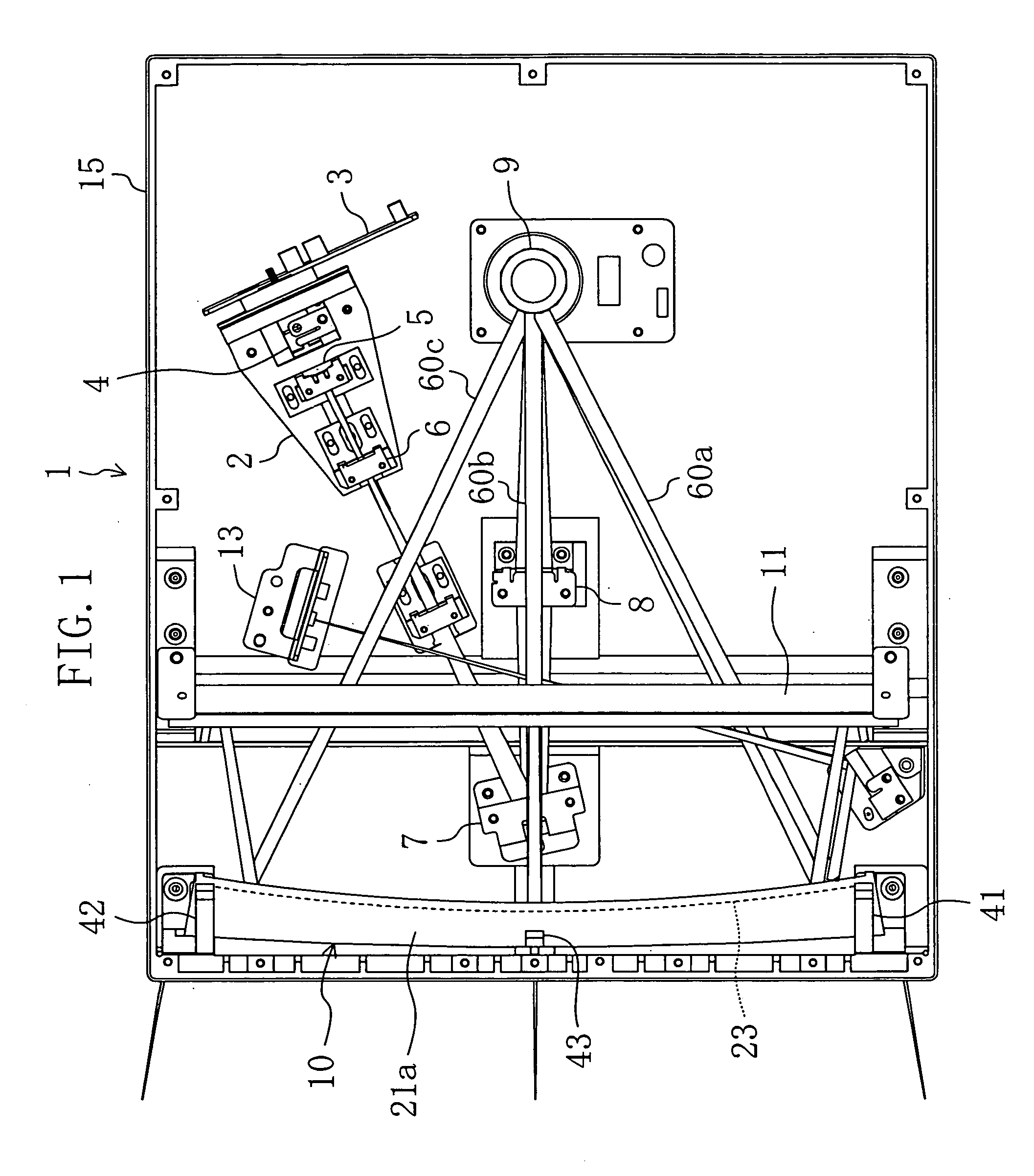
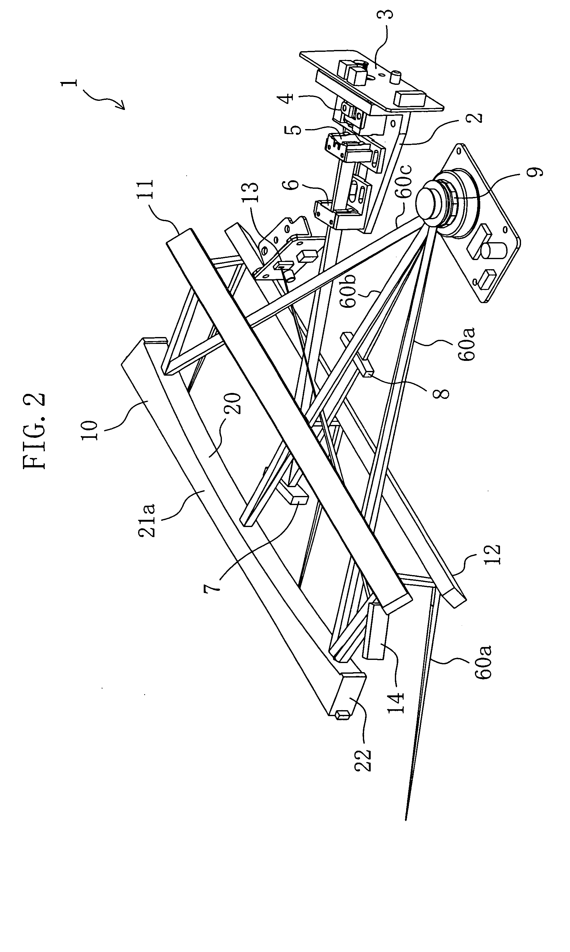
[0111] As shown in FIGS. 1 and 2, an optical scanner 1 according to this embodiment includes a light source unit 2, a polygon mirror 9, a reflector 10 and a synchronization sensor 13. These members are provided in a case 15. Note that the right hand side of FIG. 1 is referred to as a “rear side” and the left hand side of FIG. 1 is referred to as a “front side” for convenience.

[0112] The light source unit 2 is formed of an assembly of a laser driving substrate (which will be hereinafter referred to as a semiconductor laser) 3 in which a semiconductor laser circuit is provided, a collimator lens 4, a main concave cylinder lens 5 and a sub convex cylinder lens 6. In the direction in which laser light of the light source unit 2 is irradiated, i.e., in the front of the light source unit 2, a deflecting mirror 7 is provided. A main convex cylinder lens 8 is provided between the deflecting mirror 7 and the polygon mirror 9.

[0113] The collimator lens 4, the main concave cylin...

Example

Embodiment 2

[0139] As shown in FIG. 8, in an optical scanner 1 according to this embodiment, the first, second and third support points S1, S2 and S3 are provided so that the center of gravity G of the reflector 10 is located inside of the imaginary triangle V3 joining the support points S1, S2 and S3 when viewed from the top. Moreover, although illustration is omitted, a shear center of a cross section of reflector 10 in the center potion in the long side direction is located inside of the imaginary triangle V3. In other points, the optical scanner of this embodiment is substantially the same as the optical scanner of EMBODIMENT 1.

[0140] As described above, in the optical scanner 1, the reflector 10 is supported so that the center of gravity G is located inside of the imaginary triangle V3 joining the support points S1, S2 and S3. Thus, even when an external force (e.g., a vibration of the motor of the polygon mirror 9 and external impact) is applied to the reflector 10, the refl...

Example

Embodiment 3

[0154] An image formation apparatus according to this embodiment includes the optical scanner 1. Next, embodiments of an image formation apparatus in which the optical scanner 1 is provided. The image formation apparatus including the optical scanner 1 can be used for various types of image formation apparatuses such as a laser beam printer, a laser facsimile machine and a digital copy machine. As the optical scanner 1, the reflector 10 according to any one of the above-described embodiments and the reflector 10 according to any one of the above-described modified examples can be used.

[0155] As shown in FIG. 11, the optical scanner 1 (illustration of the case 15 and other elements is omitted) including the light source unit 2, the polygon mirror 9 and the reflector 10 is stored in a casing 51 an image formation apparatus 50. Moreover, in the casing 51, a photosensitive drum 16, a primary charger 52 for attaching electrostatic ions to a rim surface of the photosensitive...


PUM


Abstract

A reflector 10 is formed so as to have a long side along a scanning direction of a ray bundle. The reflector 10 includes a thin-plate-shaped reflector body having one plane to be a reflection plane 20 and upper and lower ribs 21a and 21b each extending from the reflector body in a back side. The reflector plane 20 is formed of a curved plane having positive power at least in the scanning direction, i.e., a so called free-form plane. The reflector 10 is supported by protrusions 31, 32 and 33 at three points, i.e., first, second and third support points S1, S2 and S3 located in the vicinities of one end portion of the reflector, the other end of thereof, and a center portion thereof, respectively. A distance L1 between an imaginary straight line V1 joining the first and second support points S1 and S2 and the third support point S3 is larger than a sag L2 of the reflector 20. The center of gravity G of the reflector is located inside of an imaginary triangle V3 joining the first, second and third support points S1, S2 and S3.

Description

CROSS-REFERENCE TO RELATED APPLICATION [0001] The disclosure of Japanese Patent Application No. 2003-369479 filed on Oct. 29, 2003 including specification, drawings and claims and the disclosure of Japanese Patent Application No. 2003-383437 filed on Nov. 13, 2003 including specification, drawings and claims are incorporated herein by reference in its entity. BACKGROUND OF THE INVENTION [0002] 1. Technical Field to which the Invention Belongs [0003] The present invention relates to a method for supporting a reflector in an optical scanner, an optical scanner, and an image formation apparatus including the optical scanner. [0004] 2. Prior Art [0005] Conventionally, optical scanners have been used for image formation apparatuses such as laser beam printers, laser facsimile machines and digital copy machines. As an optical scanner of this kind, an apparatus including a semiconductor laser as a light source, a polygon mirror (rotating polygon mirror), a first image formation optical sys...

Claims


Application Information

Patent Timeline
IPC IPC(8): G03B15/02
CPCG03B15/02
Inventor YOSHIKAWA, MASANORIHIROSE, HIDEONAKANO, MASAAKIKATOU, IKUKOFUJIMOTO, KEISUKE
Owner PANASONIC CORP
Why Eureka
Try Eureka